Dear TI experts:
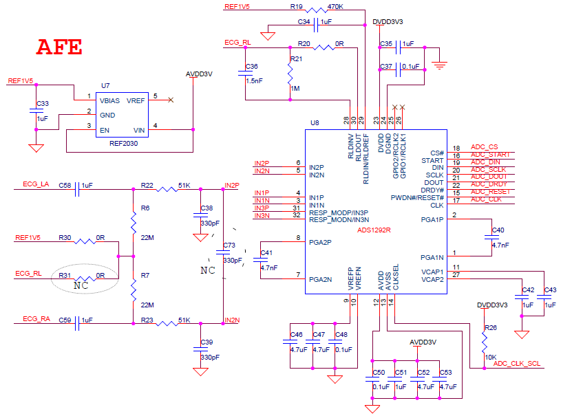
I have a project that I need use ADS1292 for 1-LEAD ECG application. I only use 2 electrode to measure 1-Lead ECG without RLD .In this case,These electrode inputs must be AC-coupled,so how to realize the function of lead off? THX
Dear TI experts:
I have a project that I need use ADS1292 for 1-LEAD ECG application. I only use 2 electrode to measure 1-Lead ECG without RLD .In this case,These electrode inputs must be AC-coupled,so how to realize the function of lead off? THX