This thread has been locked.

If you have a related question, please click the "Ask a related question" button in the top right corner. The newly created question will be automatically linked to this question.

ADS1299: A strange phenomenon regarding ADS1299 data output

Part Number: ADS1299

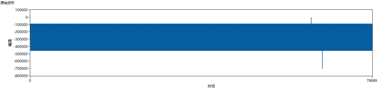
I used ADS1299 to collect 10HZ, 100MV square wave signal. After a while, my host computer showed a mutation. I used a logic analyzer to collect the SPI pin level and found that the output data of the ADS1299 was repeated. As shown below.

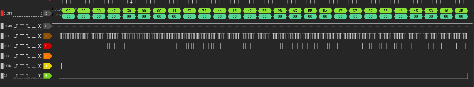
The channel data after the second C0 00 00 is basically the same as the normal channel data. The data output by ADS1299 is wrong. Why does this happen?

  • Hi,

    I'm having trouble understanding the problem, can you please elaborate? 

    Can you please provide additional detail on the test setup? 

  • HI,

    I really appreciate receiving your reply.

    Maybe there is something wrong with my narrative, so that you cannot understand the question I am asking.

    My problem is that in the picture I posted above, there is some problem with the data output by the ADS1299, causing my data to mutate, such as the picture below me.

    I found the electrical signals collected by the logic analyzer corresponding to the mutation data. I found that the misalignment of the output data of the ADS1299 was the main reason for my data mutation. The correct data format output by ADS1299 is: C0 00 00 (24 status bits) + the first channel (24 bits) + ........ + the eighth channel (24 bits), the wrong data format I encountered Yes: C0 00 00 (24 status bits) +47 C0 00+ 00 (24 status bits appear again) and the subsequent channel value is correct. But the correct bits of the entire data are shuffled.

    The above is the problem I encountered.

    Below is my register configuration.

    CONFIG1    0x94

    CONFIG2     0Xc0

    CONFIG3     0XE0

    LOFF: Lead-Off Control Register         0X00

    CH1SET       0X00

    CH2SET        0X00

    CH3SET (My main test channel)       0X00

    CH4SET(EEG test channel)        0X60

    CH5SET  (EEG test channel)     0X60

    CH6SET        0X00

    CH7SET        0X00

    CH8SET        0X00

    Other register configurations are default.

    My ADS1299 is initialized by setting START to high to start the conversion.

  • Thank you for the additional detail.

    I recommend that you check you SPI settings; spi settings. SCLK speed using the posts here:https://e2e.ti.com/support/data-converters/f/73/p/772058/2855202

    Also, do you see DRDY go low at any time? Using the SPI communication post in the link above, can you verify that DRDY pulses properly upon power-up?

  • HI

    I am grateful to receive your recovery。

    DRDY is reduced regularly according to the 1K rate I set.I think the ADS1299 device is normal.

    This may happen because my SPI related programs are not normal.

    I am modifying my SPI related program.

    I will contact you if other abnormal conditions occur.