This thread has been locked.

If you have a related question, please click the "Ask a related question" button in the top right corner. The newly created question will be automatically linked to this question.

ADS1292R: RLD not working and ECG is running away form 0 line

Part Number: ADS1292R
Other Parts Discussed in Thread: ADS1292

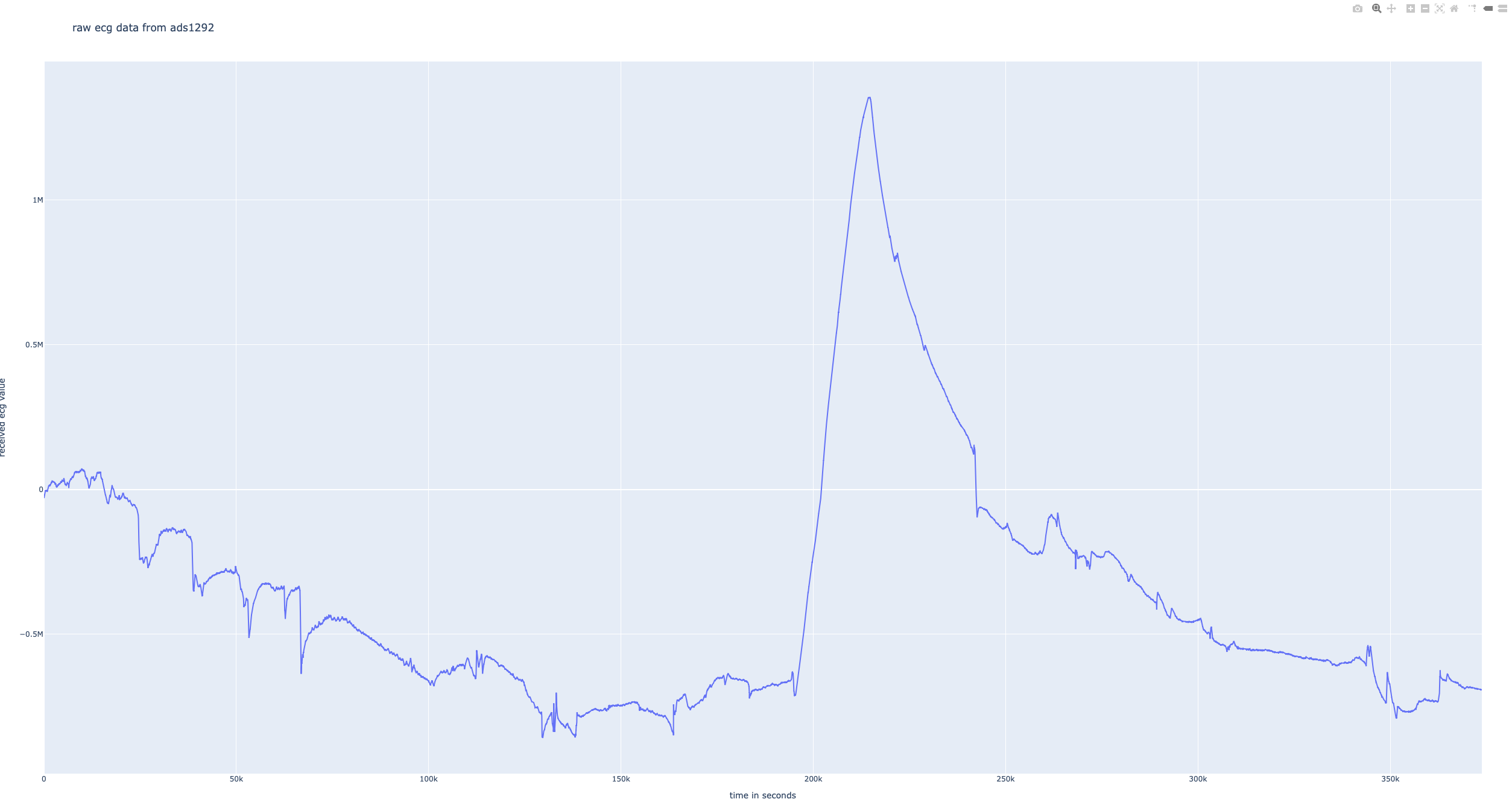
Hello we made our integration with the ECG chip and we have the problem that the ECG is moves around a lot and not stays by the 0 line. Please have a look at the html file but as preview you can see that pic. On the html file you can zoom. 

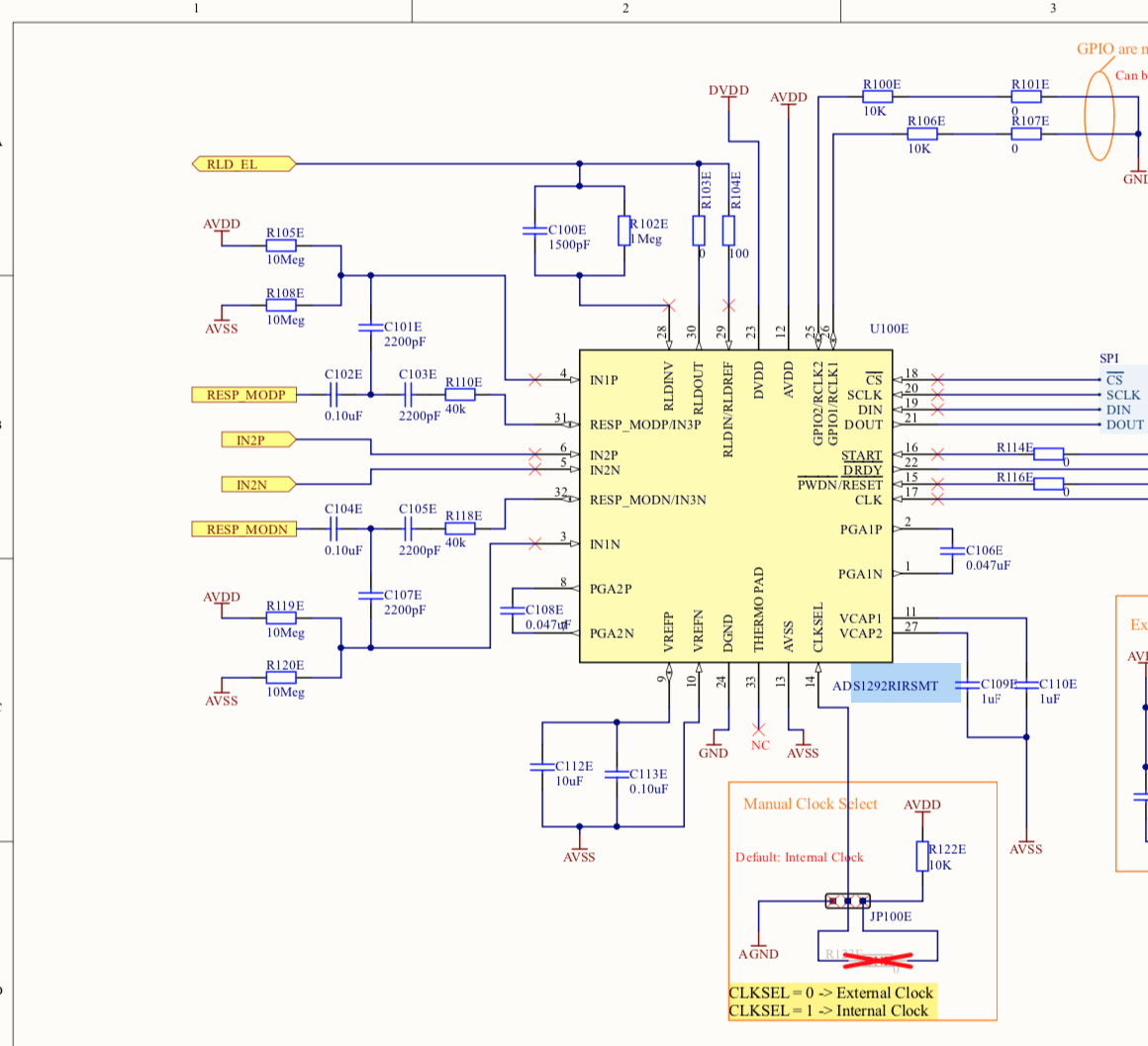
When we did the schematic our HW developer was in contact with Tom from TI and the Schematic was changed to our needs together with him. We are using the ecg electrodes very close together only 3cm distance. 

In the PDF file you can see out init process for the Chip and which settings we are using. 

Can you please tell us what could be wrong and why the RLD is not working so the ECG is moving a lot and not realy stays on the 0 line?

Thank you 

Regards Marc

ADS1292 documentation.pdf

ads1292_10696.html

  • Hello,

    Thank you for your post. The detailed documentation and results plot is much appreciated!

    At first glance, this appears to be an input impedance issue. Perhaps the electrode-skin contact impedance isn't stabilizing or is widely mismatched between the two electrodes. Are these dry electrodes?

    I reviewed your register settings and initialization sequence and I don't see any obvious errors. One suggestion might be to try disabling the lead-off current for now by setting all LOFF_SENSx bits to 0. If the electrode contact impedance is large and non-constant, the 6-nA lead-off current may create an unstable DC offset. 

    Best regards,

  • Hello thank you for your msg.

    The measurement was on a Animal with cot. On this measurement we add ECG gel. Why you asking? Do you think this comes all form a changing contact?

    We tested the other settings and it looks the same to me. We notice that our schematic have some difference to the reference design where we don t remember why they are there. Can you please confirm that the schematic is fine?

    thank you

    regards,

  • Hello,

    Yes, I was supposing that the contact quality may have been poor and unstable. If the contact impedance is changing, the DC baseline will shift.

    I would reduce the differential capacitor on Channel 2 (C108E) from 47 nF to 4.7 nF. 

    If you have any concerns about the EVM reference design and how it compares to your schematic, please don't hesitate to ask and we can try to clarify them for you.

    Best regards,

  • Hello,

    so what do you need to clear this question?:

    If you have any concerns about the EVM reference design and how it compares to your schematic, please don't hesitate to ask and we can try to clarify them for you.

    in the first post you can see the schematics....

    Thank you very much

    Regards Marc

  • Hi Marc,

    Have you tried disabling the electrode lead-off current? By minimizing the current present in each electrode wire, and by reducing the contact impedance with the gel, you might create a more constant DC baseline.

    Another suggestion would be to verify the operation of the RLD loop by measuring the RLDOUT signal. To do this, change the MUX setting on Channel 1 to MUX1[3:0] = 0010. The output of Channel 1 will become [RLDOUT - RLDREF] x PGA gain. This will tell how you the output of the RLD amplifier is changing in response to the common-mode signal sensed at the output of Channel 2. Ideally, the output of this internal RLD measurement would be centered around 0 V, but this may vary depending on how much current the RLD amplifier is sourcing/sinking to drive the body. The AC component of the RLDOUT signal will be the inverted common-mode signal sensed at the output of Channel 2 (per your register settings).

    Best regards,