This thread has been locked.

If you have a related question, please click the "Ask a related question" button in the top right corner. The newly created question will be automatically linked to this question.

CCS/ADS1256: This ADS1256 measures less than 5V

Part Number: ADS1256

Tool/software: Code Composer Studio

Hi everyone.

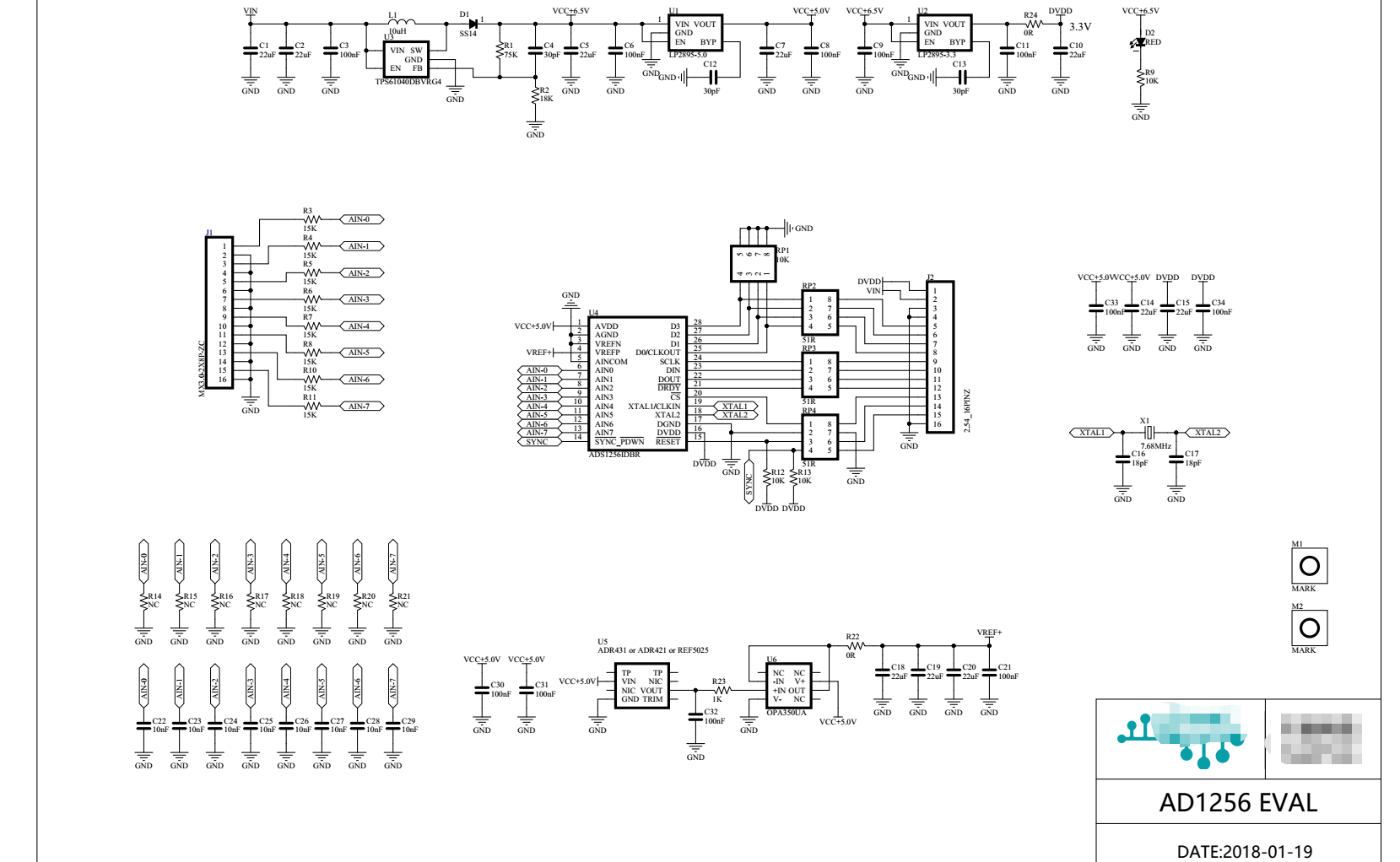
Recently I was debugging the ADS1256 chip, and I used a regulated source as the input voltage.

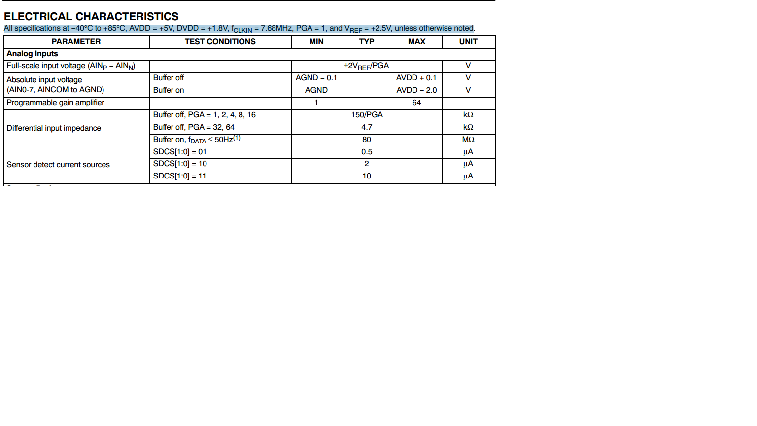
When the input voltage reaches above 3.8V, for example, the measured voltage of 4V and 5V is still 3.8V.Measured value below 5V.According to the data sheet, the measurement range is -0.1-5.1V

1.This BUFFER is Disabled.   

2.The PGA is 1.   

3.Auto-Calibration Disabled. 

4. The Data Rate Setting  is 10sps 

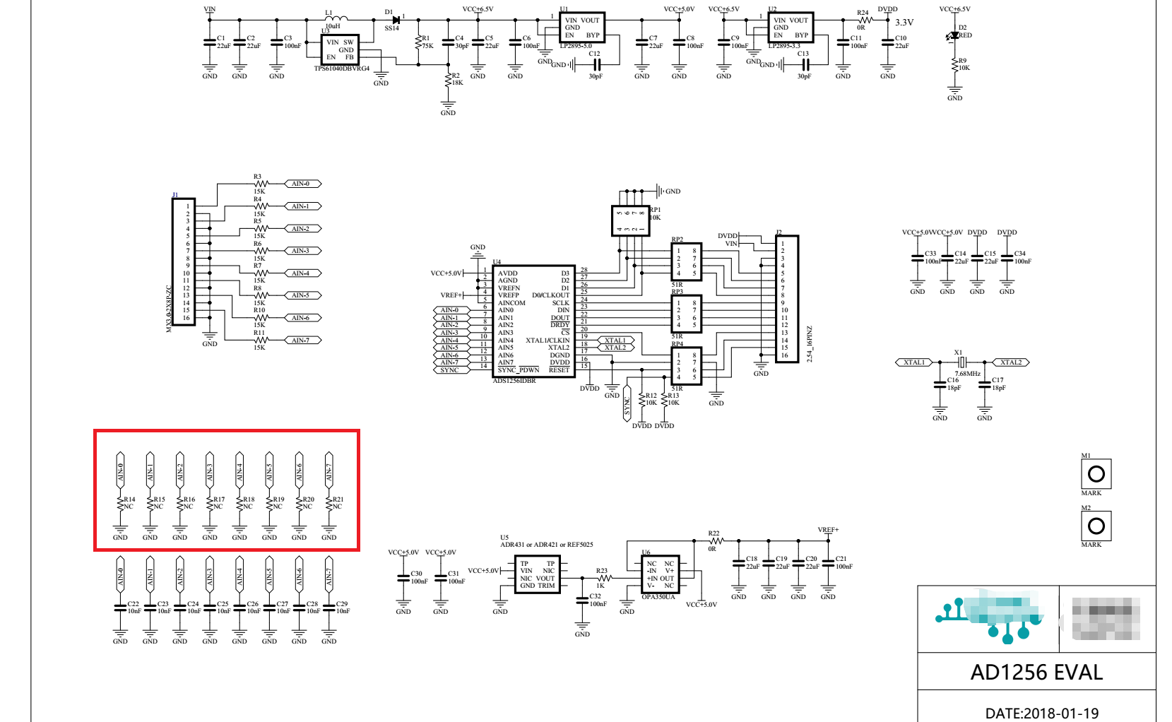
5. With single-channel input.

6.Is that register able to set the range, or is the configuration incorrect?

Ask an official engineer for help.Thank you!

  • Hi Lin Shi Chang,

    Can you send me your schematic and the complete register settings you are using?  Can you give me details on how the analog input source is connected to the ADS1256?  What are you using for the reference to the ADS1256? To measure up to 5V you need a 5V reference.

    Does the analog input source have a ground that is also connected to the analog ground of the ADS1256?  An AC powered source used as the analog input can have a relative output that may be much different between the source and the AVDD supply for the ADS1256.  The external voltage input source (-) lead should also be connected to analog ground as well as one of the analog inputs to make sure the source is within the correct input range of the ADC.

    Best regards,

    Bob B

  • Hi Bob B

    1.Can you send me your schematic and the complete register settings you are using?  

    The register setting:STATUS REGISTER:0x30      MUX:0x58  ADCON:0x00  DRATE:0x23  GPIO Comtrol Rehister :0x00

    2.Can you give me details on how the analog input source is connected to the ADS1256?

    The Input connect the channel 5.The GND connect the analog ground.

    3.What are you using for the reference to the ADS1256? To measure up to 5V you need a 5V reference.

    But,the data sheet means the ref is 2.5V.Can this be changed?

    4.Does the analog input source have a ground that is also connected to the analog ground of the ADS1256?

    YES

    Best regards,

    lin shi chang

  • Hi Lin Shi Chang,

    I apologize for my mistake.  Many of the Delta-Sigma ADCs have a full-scale range of +/-VREF/GAIN whereas the ADS1256 is actually +/-2*VREF/GAIN as you correctly pointed out. So 2.5V is the correct reference voltage to use to achieve a full-scale range of +/-5V.  As you are measuring a single-ended input, you will only see the positive 1/2 of the full-scale range as shown in Table 16 on page 23 of the ADS1256 datasheet.

    In hex format the output code will vary from 0x000000 to 0x7FFFFF (excluding offset and noise).  Can you send me the output code (raw hex preferred) you are seeing for the various input voltages you are using?

    One thing to consider is that you are using a 15k Ohm input resistance and with the buffer disabled the input impedance to the ADS1256 is 150k.  This will create a voltage divider at the input.  The voltage drop across the input resistor is rather significant and is nearly 0.5V with a 5V input.  This will also reduce the measured input voltage to much less than 5V.  You may wish to lower the input filter resistance to a much smaller value.  There will still be an error, but much smaller.

    Best regards,

    Bob B

  • Hi Bob B

    0V     ------   0xfad3

    3.3V   -----  0x5552ef

    5V      -----   0x63959c

    So,What should I do to truly measure to 5V?

    Best regards,

    lin shi chang

  • Hi Bob B

    I open the BUFFer and setting the PAG is 2.Then add a attenuation resistance in the Red area.

    I don't know if this solution is feasible.

  • Hi Lin Shi Chang,

    By enabling the buffer you will increase the input impedance considerably reducing the error created by the input filter resistor.  However, by adding the additional resistor to create an external voltage divider you will have error due to the mismatch of resistors and any temperature drift that may change the values of resistance.  Is there a specific reason as to why you need to have 15k Ohms as the input resistor with the buffer disabled (as opposed to 1K for example)?  Also, have you tried the external voltage divider while enabling the buffer to see if the condition improves?

    Best regards,

    Bob B

  • Hi Bob b,

     Is there a specific reason as to why you need to have 15k Ohms as the input resistor with the buffer disabled (as opposed to 1K for example)?


    The supplier stated that this 15K Ohms is to prevent the input voltage from exceeding the chip range and protect it.Now I replace the 15K Ohms with 100 Ohms, and the error becomes very small.

    Have you tried the external voltage divider while enabling the buffer to see if the condition improves?


    no,I think the above scheme is better.so,I didn't try.

    Best regards,

    Lin Shi Chang