This thread has been locked.

If you have a related question, please click the "Ask a related question" button in the top right corner. The newly created question will be automatically linked to this question.

ADS1118: Input Buffer

Part Number: ADS1118
Other Parts Discussed in Thread: ADS1018

Hi,

I want to realize the following function.
--------------------------------------------------
Input Stage
    RESISTIVE DIVIDING  3V->2V
    LPF  fc=1Hz
--------------------------------------------------

But,
> 10.2.2 Detailed Design Procedure
> TI recommends limiting the filter resistor values to below 1k.
So do I need to insert a buffer?

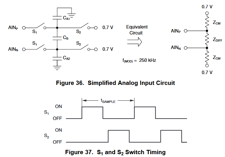
The PGA is not a buffer, to drive a switched-capacitor?

Best Regards,

Tomoya


  • Tomoya-san,


    I think that you need the buffer but there are a few things that I would point out.

    First, do you really need a 16-bit ADC? The ADS1118 is a 16-bit device and you may be able to use the less-expensive ADS1018 which is a 12-bit device. Of course, if your measurement is single-ended, the ADS1118 acts as a 15-bit single-ended ADC and the ADS1018 would be an 11-bit ADC, but you may be able to tolerate the error.

    For your voltage divider, you are already have some error because Ra and Rb are 1% resistors. Without the buffer, you would also need to look at the input impedance of the ADC. For this device, the switched capacitor input looks similar to an input impedance like this:


    A write-up on this input can be found in the ADS1118 datasheet on page 19. The resulting differential and common-mode input impedance is dependent on the FSR. This is shown in the electrical characteristics curves on page 7 of the datasheet shown below.


    With the FSR set to ±2.048V, the differential and common-mode input impedance are about 4.9MΩ and 6MΩ which with the equivalent output impedance of the voltage divider could add a couple of percent of error.

    Additionally this large output impedance of the measurement disrupt the input sampling of the ADC with a large series resistance going to the sampling capacitor. This may show up as a larger offset error and gain error in the measurement.

    Because of all these reasons, I would use some buffering in the measurement or use a lower resistance voltage divider ~10kΩ.


    Joseph Wu

  • Hi, Joseph

    Thank you for your kind reply.
    I understood that it would be better to add a buffer.

    Tomoya