This thread has been locked.

If you have a related question, please click the "Ask a related question" button in the top right corner. The newly created question will be automatically linked to this question.

ADS8028: Temp sensor output value error at electromagnetic field immunity test

Part Number: ADS8028

Hi Expert,

My customer have an issue about temp sensor output value error at electromagnetic field immunity test.

Test : IEC61000-4-3 RI, 10V/m 80MHz

Temp sensor output value become unstable between 20C and 60C at electromagnetic field immunity test. (ADC values are stable)

Q1. Could you please let me know about internal circuit for Temp sensor? decupling cap, etc 

      It may be difficult to disclose the information. How do you think about the internal temp sensor to influence from EMC?

Q2. If they read the temp sensor value when TM_BUSY is low unintentionally, will the read results be unstable?

Thanks

Muk

  • Hello Muk,

    1. We do not have information about how the temperature sensor will behave under EMF. But when you say unstable, are the readings completely wrong? or is there a shift. How exactly is it unstable? does it behave as expected at other temperatures outside of 20C to 60C?

    Overall, we suggest using good shielding and coupling at the power supplies.

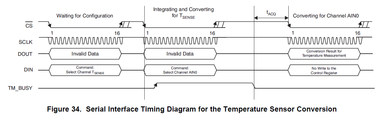
    2. Below is a timing diagram of configuring and reading out the Temp sensor data.

    The Control Register needs to be set for the temperature sensor to convert, this is the first frame

    The second frame, when BUSY is high, this indicates that temp sensor data is being converted, but the data will not be outputted until the next frame when BUSY is then low, the third frame.

    Regards

    Cynthia

  • Hi Cynthia-san,

    Please refer the following read values gruff.

    It seems random. 

     X : measurement times(F=around 4sec), Y : Temp sensor read value *C


    It was measured by room temp. but ADS8028 is sealed inside their system.

    Sometimes, the read result become over 75C. then, their test was Fail. 

    Also, in case of normal situation (not EMF), then, it was no problem. 

    As your mention, we should suggest using good shielding and coupling at the power supplies.

    Do you have any idea for specific method of the shielding and coupling at the power supplies? Could you please let me know it.

    By the way, the read values between AIN0 and AIN7 are no problem. Are temperature sensors susceptible to noise?

    (Additional question)

    Conversion time for  AINx is 700ns

    Conversion time for  Temp sensor is 100us

    Could you please let me know the reason of difference between AINx and Temp sensor?

    Customer want to know the Temp sensor's internal mechanism and sequence. 

    Thanks

    Muk

  • Could you please help my questions?

  • Hello,

    Apologies for the delay due to holidays. I am reaching out to our design team to get more information about the internal temp sensor.

    Until their response, I will not be able to say if the temp sensor is more susceptible to EMF, and if so how.

    Since it is completely internal, it will be hard to compensate. Firstly I would suggest large solid ground planes and well sized decoupling caps on the power supplies.

    From there, shielding can look different based on the application. one can add a physical cover over the device on the PCB, shielding cable can be used, and such.  If you would like to speak about this in further detail, feel free to email me.

    Regards

    Cynthia


  • Hi Cynthia-san,

    Thank you for your response.

    I wait the design team feedback.

    Thanks

    Muk

  • This has been moved to an internal email.

    Regards

    Cynthia