Other Parts Discussed in Thread: ADS1299
Hello,
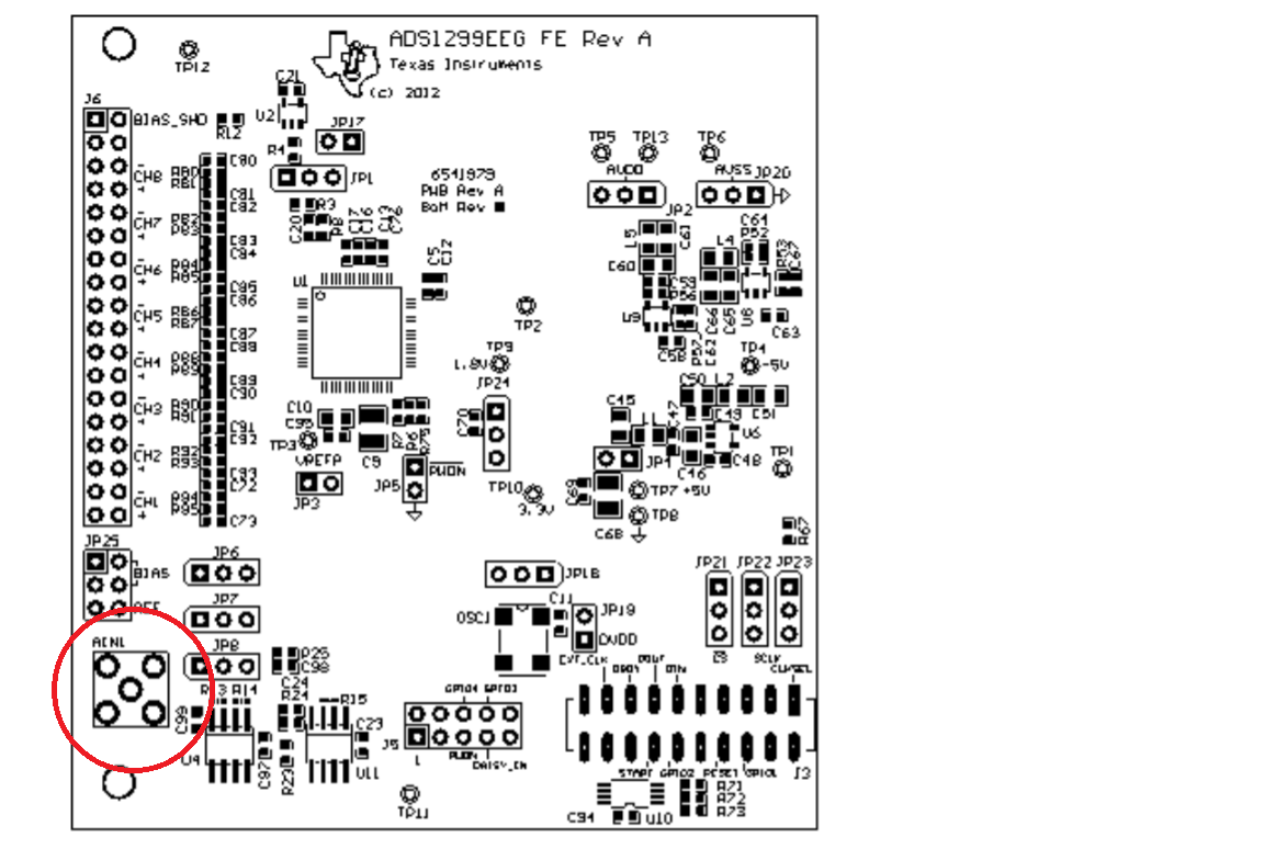
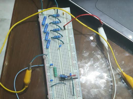
I am trying to setup a four channel eeg measurement device, I have connected the following :
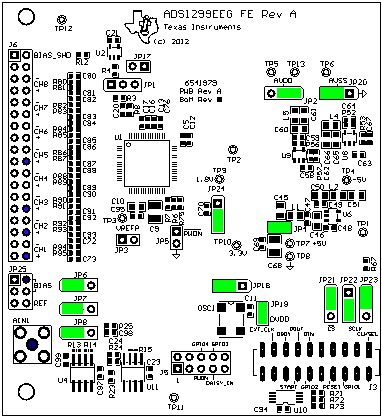
As you can see i have connected only positive inputs to channel 1,2,3,5 and shown in blue and i have attached an electrode to JP25 2 for bias also shown in blue, and finally an electrode to AIN1 for reference in blue and there respective pins as mentioned on the datasheet.
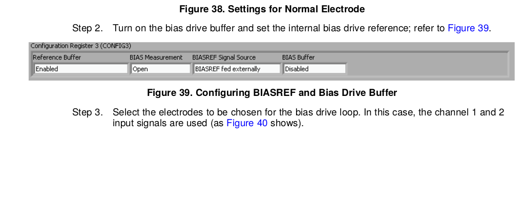
My problem is with setting the bits in the different registers, i powered down all unwanted channels, i set the SRB1 bit to high, and the rest to normal electrode mode, however i do not understand the SRB2 bit and the bias driver bits, and how it routes to the bias feedback voltage?
could you provide some insight ? on whether the setup is right or needs any tweaking and how to set the bits for SRB2 and bias driver circuit.
Many thanks
Karam Jaber E.E