This thread has been locked.

If you have a related question, please click the "Ask a related question" button in the top right corner. The newly created question will be automatically linked to this question.

ADC12DJ5200RF: The waveform appears to be modulated

Part Number: ADC12DJ5200RF
Other Parts Discussed in Thread: LMH6401

Hi,

I am currently designing a board with an ADC12DJ5200 RF.
The circuits and ICs around the ADC were designed with reference to the EVM.
When the waveform input on the prototype board is plotted on a graph, the waveform may look as if it were modulated at 5.2 GHz.
Today's measurements were made in the following order.

cold start
66 MHz input
100 MHz input
133 MHz input
200 MHz input
1 GHz input
50 MHz input
66 MHz input
100 MHz input
133 MHz input
200 MHz input
1 GHz input


At first, only the 100 MHz input signal was not modulated at 5.2 GHz, and in the 2nd measurement, only the 100 MHz input signal was modulated at 5.2 GHz.
What could be the cause of the different results when all the environment except the input frequency is not modified?

  • Hi,

    Just to be clear. Is the data that you are taking and the data you sent from the 5200RF EVM? Or some other board that it had been designed into?

    If from the 5200 EVM. Can you please let me know what JMODE and any other setup features chosen? If would also be helpful to send some FFT plots as well?

    Regards,

    Rob

  • fftdata.xlsxHi,

    This is not the waveform obtained by the EVM, but the waveform obtained by the board I designed.

    This board I made operates with the setting of JMODE 1.
    When I performed the FFT, it appeared that a signal with a higher frequency than the input frequency appeared.

  • Hi,

    Thank you for the update and FFT data.

    It looks like the data capture is real and the imaginary FFT. Is the setup using windowing? Uncoherently sampling? Because the sinewave looks to be cutoff in the first set of data.

    Keep in mind in JMODE1 the ADC is configured for dual edge sampling, so there will be an Fs/2 & Fs/4 spurs in the spectrum.

    If this is a board that was designed by you, can you share some more information about this board? Schematic or block diagram? Or additional information about the test setup?

    Regards,

    Rob

  • Hi,

    Thank you so much for your help.


    I was making measurements without using window functions.

    In my measurement, I keep inputting a sine wave of a constant frequency to the board.


    Data from AD is received by setting the control flag from PC, and reception is stopped by disabling the control flag from PC.
    The obtained hex value data is converted into dec value by the program and plotted on the graph.

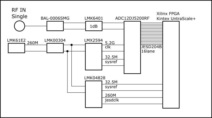
    I think my circuit is similar to EVM.
    I attach a simple block diagram.

  • Hi,

    Yes, you are welcome!

    If not windowing, are the clock and analog input frequencies locked with a reference?

    That might be the case. Also what happens if you change the sampling rate of the ADC? Same problem?

    If you have a schematic you can pass of the board that might be helpful as well. I can check the analog input setup with the amplifier/LMH6401.

    Regards,

    Rob

  • Hi,

    I will try to find out what happens when I change the sampling frequency.


    The circuit from the SMA connector to the input of the ADC is shown below.
    Because the original circuit diagram spans multiple pages and is difficult to refer to, I have extracted only the analog input.

    The LMK6401 has the following settings:.
    R02: 0x19
    R04: 0x27
    R05: 0x45

  • Hi,

    I will have to look into the LMK register settings.

    In the meantime, I would put some AC coupling caps between the output of the LMH6401 amplifier to the inputs of the ADC.

    This will help decouple the common mode voltage of the two devices.

    Let me know what you find using a different sampling rate.

    Regards,

    Rob

  • Hi,

    I tried to run the ADC at 3.2 GHz or 4.2 GHz, but most of the time the LMX frequency wasn't right and it was very hard to configure.

    Setting the LMX to 5.2 GHz output is easy, but trying to set it to 4.2 or 3.2 GHz has only seen 1 success between countless retries. Even after one success, the

    JESD link could not be established and data could not be obtained.

    The output of the LMK 61 e2 is set at 1/20 and the sysref is set at 1/160 as a ratio with respect to the clock of the ADC.

    It was confirmed that the actual outputs of LMK 61 e2 and LMK 04828 were as set.

    The output of the LMX was about 3.6 GHz each time.

    settings.zip

  • Hi user5788058,

    Please find the attached files these files should generate 3.2G clock with 160M ref and 4.2G with 210M ref respectively.

    Regards,

    Neeraj

    LMX2594_3200M_160M.cfg

    LMX2594_4000M_200M.cfg

  • Hi,

    I was able to run AD with 8Gsps by the way you taught me. Thank you very much.

    When operating at 8 Gsps, a spectrum with a higher frequency than the target frequency was observed.

    Since it is close to 4 GHz, the mysterious high frequency component appears at a value close to the sampling clock of the ADC.

    It has been confirmed that this does not occur even if the same signal is input to the EVM and data is taken at the same sampling interval.

    data20200110.xlsx