Part Number: AMC7834EVM
Other Parts Discussed in Thread: AMC7834, LMP92066
Hello,
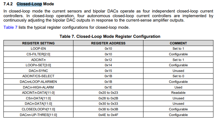
I want to set mode of closed loop operation.
can you please send an example of configuration file for this mode?
Any SW application note will great as additional addition.
thanks,
Michael