This thread has been locked.

If you have a related question, please click the "Ask a related question" button in the top right corner. The newly created question will be automatically linked to this question.

ADS1232: Does ADS1232 support single-end input

Part Number: ADS1232
Other Parts Discussed in Thread: INA128, ADS1230, ADS125H02

hello guys 

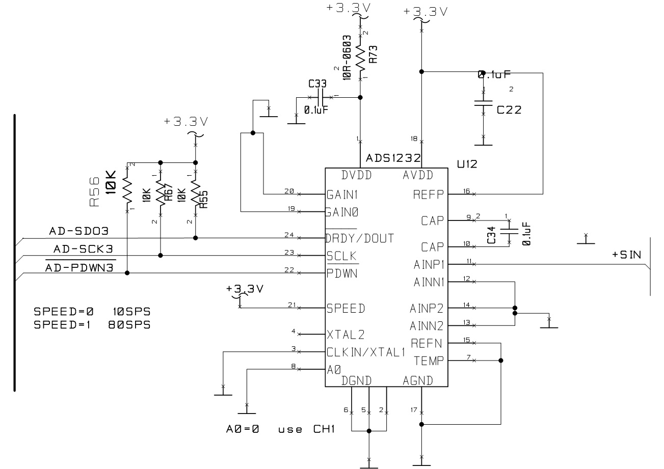
    I have used ADS1232 when EXC votage and REF is 5V.Now I have design a new product by  ADS1232 .such like this setup.

the GAIN is 1

SPEED is 80HZ

EXC votage is 10V

REF votage is 3.3V

AINP is input from by INA128.INA 128 also working right now.(I have design the P and N votage).

AINN is connecting  to the GND.

I have got the DEC,but it is very fluctation.and the linear is not very good.

So I have two questions :

1:Does ads1232 support the single-end input?At first I used ADS1230 to design,the datasheet tells us it support ,but autally it doesn't support.So,ADS1232 also like this ?

2:when the REF is 3.3V,it cann't support the single-end,or the GAIN is 1?

  • Hi Junjie,

    welcome to our forum and thank you for your interest in our data converters.

    The ADS1232 does actually support single-ended inputs when using Gain = 1. It is also fine to use a VREF = 3.3V in this case. So in principle your circuit should work okay. If you could post your schematic we could double-check if there are any other potential issues.

    How is your 3.3V reference voltage and the 10V excitation voltage created? Those should be very stable, low-noise rails in order to achieve good performance.

    For a bridge measurement we usually recommend a ratiometric measurement implementation, where the reference voltage for the ADC is derived from the excitation voltage. In your case this could be implemented by using a precision, low-drift resistor divider on the 10V excitation and create the 3.3V from there. This way you make sure that any variations in the excitation voltage do not influence the measurement result.

    Following are also a few alternate options to implement your circuit:

    • You could bias the Ref pin of INA128 to AVDD/2 of the ADS1232 and then connect the Ref pin to AINN of ADS1232.
    • Instead of a 0V / 10V excitation voltage you could implement a bipolar excitation voltage so that the common-mode voltage of the bridge output falls within the supply range of the ADS1232. That way you would not need the INA128.
    • You could use ADS125H02. This device does in principle integrate the functionality of INA128 and ADS1232 into one device.

    Regards,

  • Hi 

    I had tested your recommoned formerly.So your recommend is not useful.

    I have found the cause. I supply 3.3V to the VA and Vref .that causes the DEC very fluctation.

    NOW I suplly 5V to VA and Vref,then I have a peferct linear.

    SO pls check ADS1232's application,when I use single-end mode,I cann't use 3.3V to VA and vref.

  • Hi Junjie,

    this is very odd. If the circuit works with a 5V supply and VREF then it should also work with 3.3V.

    A few more questions:

    • When you use 5V for AVDD and REFP, do you keep DVDD at 3.3V or are you also connecting the same 5V to DVDD?
    • How do you create the 5V or 3.3V supply (linear regulators or switched-mode power supplies)?
    • What is the voltage range of the output signal of INA128 that you are applying to AINP1?

    Regards,

  • hi

       When I use 5V for ACDD and REFP ,I also  connected the same 5V to DVDD .beacuse I use a LDO to supply the power of all.

    creat 5V ,I use LP2951-5.0

    creat 3.3V, I use LP2985-3.3  .

    INA128 ,I use the gain is 64.

    I donn't thank my design is wrong,so I'm very perplexed

    now I just test the EXC voltage is 5v ,I designed it so that any EXC voltage can be used,such like 5V,or 10V, or 15V

    you can give me a email,then I can send you my full design.My campany donn't alow me show my design in public

  • Hi Junjie,

    thanks for the additional information. I am as perplexed as you are.

    Maybe one last question before sending over the complete schematic. What supply are you using for the INA128? The INA128 needs a minimum supply of 4.5V. Means if you powered the INA128 from 3.3V, then the circuit would not work properly.

    Regards,

  • INA128 donn't have any problems.I have tested it except ADS1232,I used the INA128 in other cases.PLS check the ADS1232,when it is setting gian at  1,and  SINGLE-END MODE ,VREF and VADD are 3.3V.

    I read the datasheet ,it donn't show us any mode like this.

    I also tested other Instrumentation Amplifiers that are same as before.I designed many SCH. that used the AMP,so I am always doubleing  the ADS1232,It may support any of these modes, but it does not support all of them. You should be able to analyze them from its hardware architecture

  • Hi Junjie,

    the experts for the ADS1232 are on vacation till Thursday. That is why I am helping out in the meantime. I will check with them as soon as they are back and get back to you.
    But I have no reason to believe the ADS1232 should not work in single-ended mode with Gain=1 when using AVDD = REFP = 3.3V.

    In the meantime please do confirm what supply voltage you are using for the INA128 in the 3.3V case and what the output signal levels on AINP (coming from INA128) are. As mentioned before, the INA128 will not work with a 3.3V supply.

    Regards,

  • my sensor is 3MV/V,so ,the sensor's max output is 15MV while exc is 5V.

    The gain of INA128 is 64,the INA128's power is +5V and -5V,and the INA128's max  output is 15MV*64=0.96V.that's no problem.

    when VREF is 3.3V and the gain is 1.so the ADS1232's Max input is 1.65V(1/2VREF)

    the common intput voltage range is AVDD+0.1,So my design is no problem.

    But now I tested it cann't work right.but it can work right while the AVDD and VREF is 5V.

    so I think maybe the input of common voltage is not right.

  • Hi Junjie,

    thanks a lot for those additional details. I will check with my colleagues later this week when they are back from vacation.

    Regards,

  • Hi Junjie,

    Please send the complete schematic to this email address:

    pa_deltasigma_apps@ti.com

    In particular I would like to know how you have connected the INA128 Ref input and the value of gain resistor you are using.

    Please verify that the input range is within the allowable input range by measuring the AINP input with respect to AGND.  The ADS1232 should work the same way at 3.3V as it does at 5V with respect to single-ended inputs.  One consideration is capacitive load.  When using the ADS1232 in single-ended configuration, the output of the INA128 will connect to an input sampling capacitor of the ADS1232.  I would suggest adding a value of series resistance to the input in the range 500 to 1k Ohms to reduce the loading effect of the input capacitance.  You may already have this series resistance but it does not show on the schematic snippet posted previously.

    You may have a startup issue as you are violating the required 10us for PDWN going high relative to AVDD/DVDD.  See Figure 39 on page 23 of the ADS1232 datasheet.  I would suggest once the ADS1232 is powered, you pulse the PDWN pin high-low-high to reset the device.  I would also recommend that you issue the self-offset by sending a minimum of 26 SCLKs following the pulsing of the PDWN pin.

    Lastly, can you send me actual data from the ADS1232 as raw data (for example as raw hex or binary code and not converted to decimal or voltage).  Also send me the input voltage applied for the data being returned.  I would like to more fully understand the results you are seeing for both the 5V supply and the 3.3V supply conditions.

    Best regards,

    Bob B