This thread has been locked.

If you have a related question, please click the "Ask a related question" button in the top right corner. The newly created question will be automatically linked to this question.

ADS1292R: ADS1292R data capturing issue

Part Number: ADS1292R

Hi everyone,

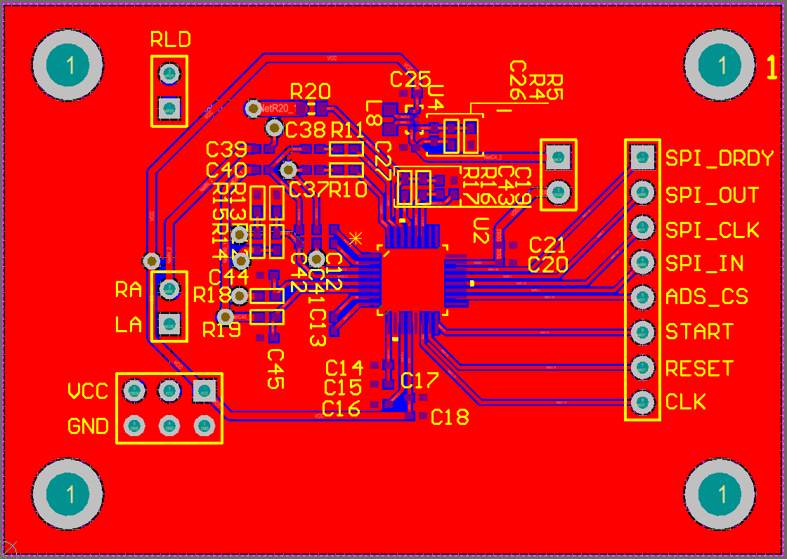
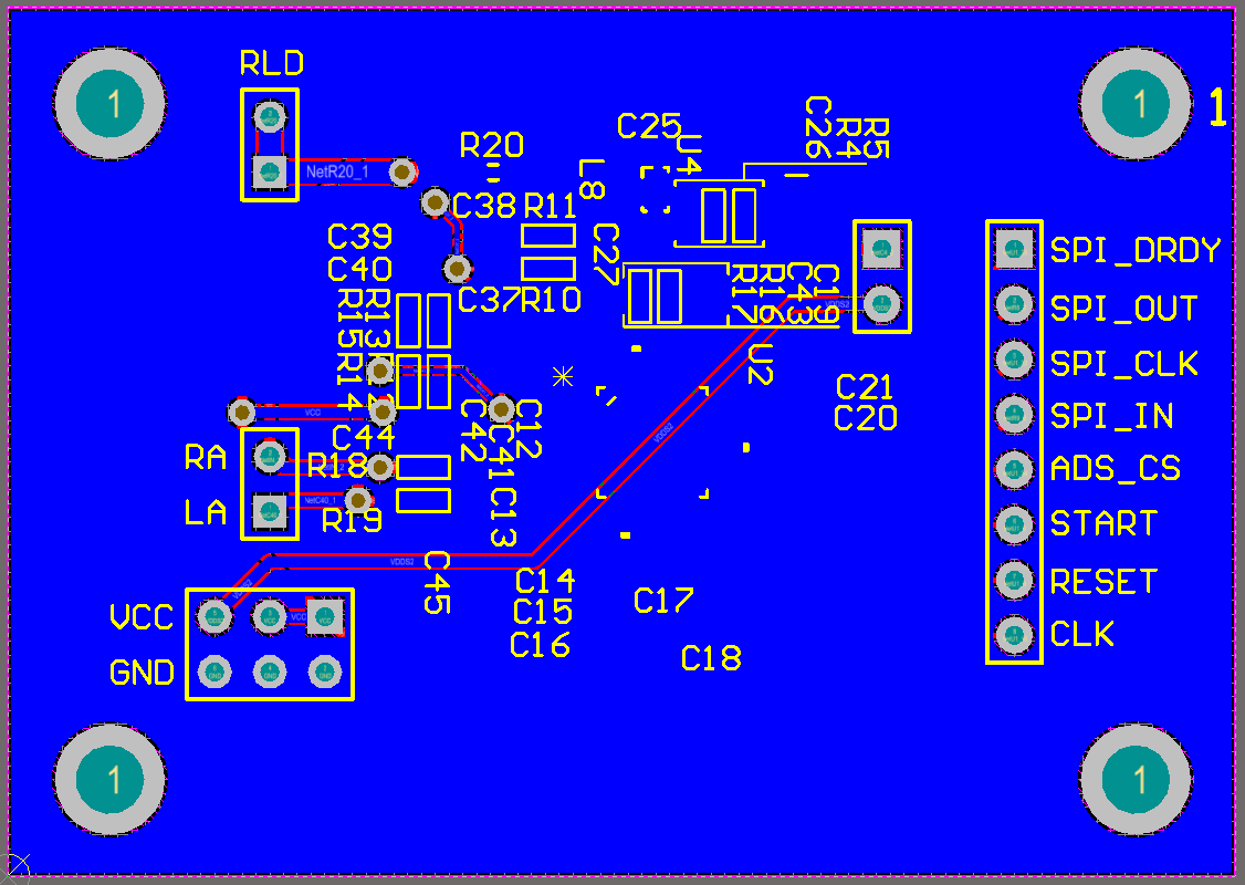
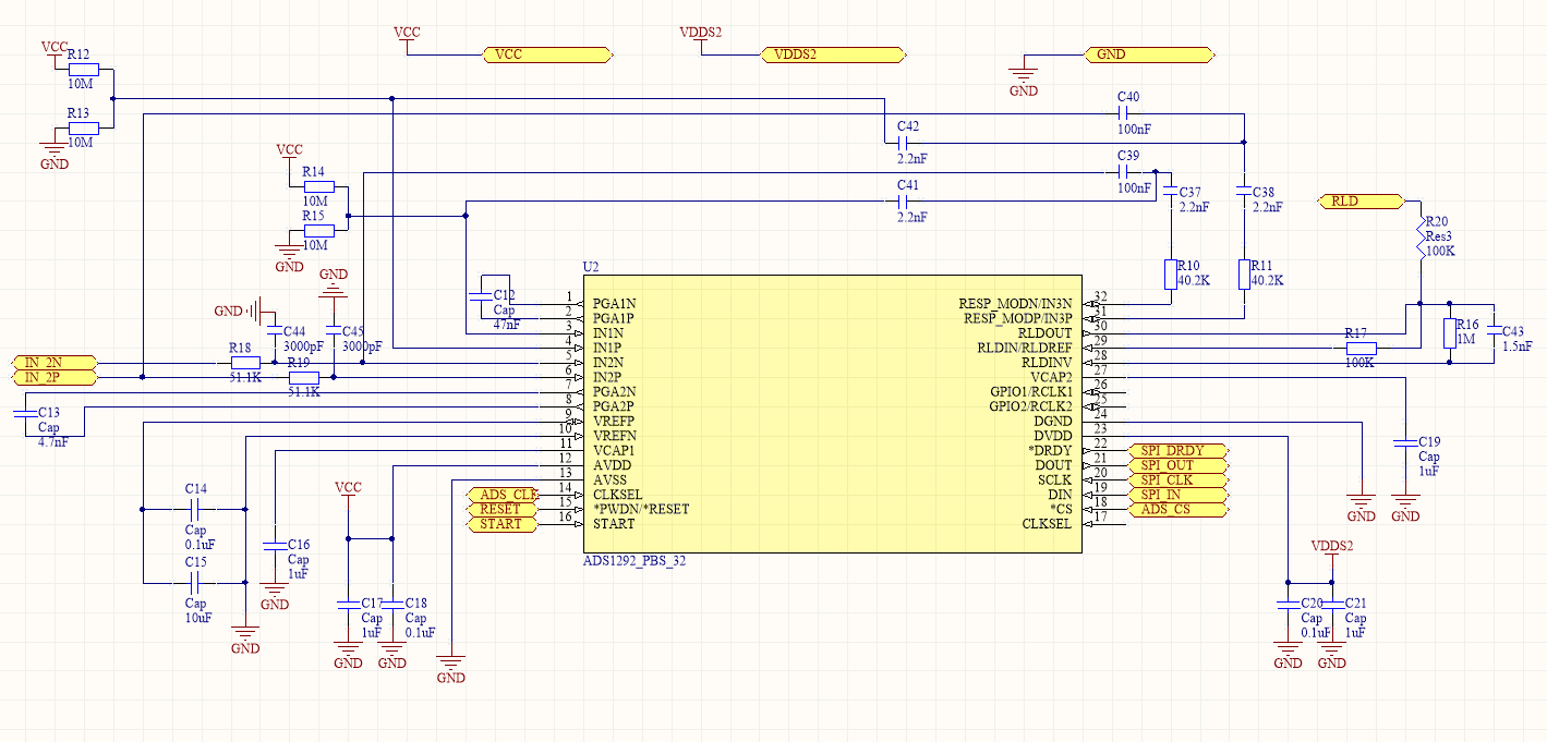
    I'm using the ADS1292R to capture ECG and respiration, and I made a custom board which has the same layout as the part of ADS1292R in MultiParameter BioSignal Monitor Design Guide.

    I gave it 3.3V in both AVDD and DVDD. Here are the problems I got:

    1. After powering on it, I set the RESET and CLKSEL pins to high. Then I send 0x11(SDATAC), 0x2000(I got the ID of 73), 0x4200A0, 0x410001, 0x440008, 0x450008, 0x4900f2, 0x4A0003 to configure the registers. After that, I send 0x08(START) and 0x10(RDATAC) through SPI. But sometimes it cannot start reading the data, it only return one frame data which is a 10-byte-long data of 0. I don't know where the issue is?

    2. When I try to capture my ECG, I got a very bad result. I did use the band pass filter and a notch filter of 50Hz. But the result is not getting better.

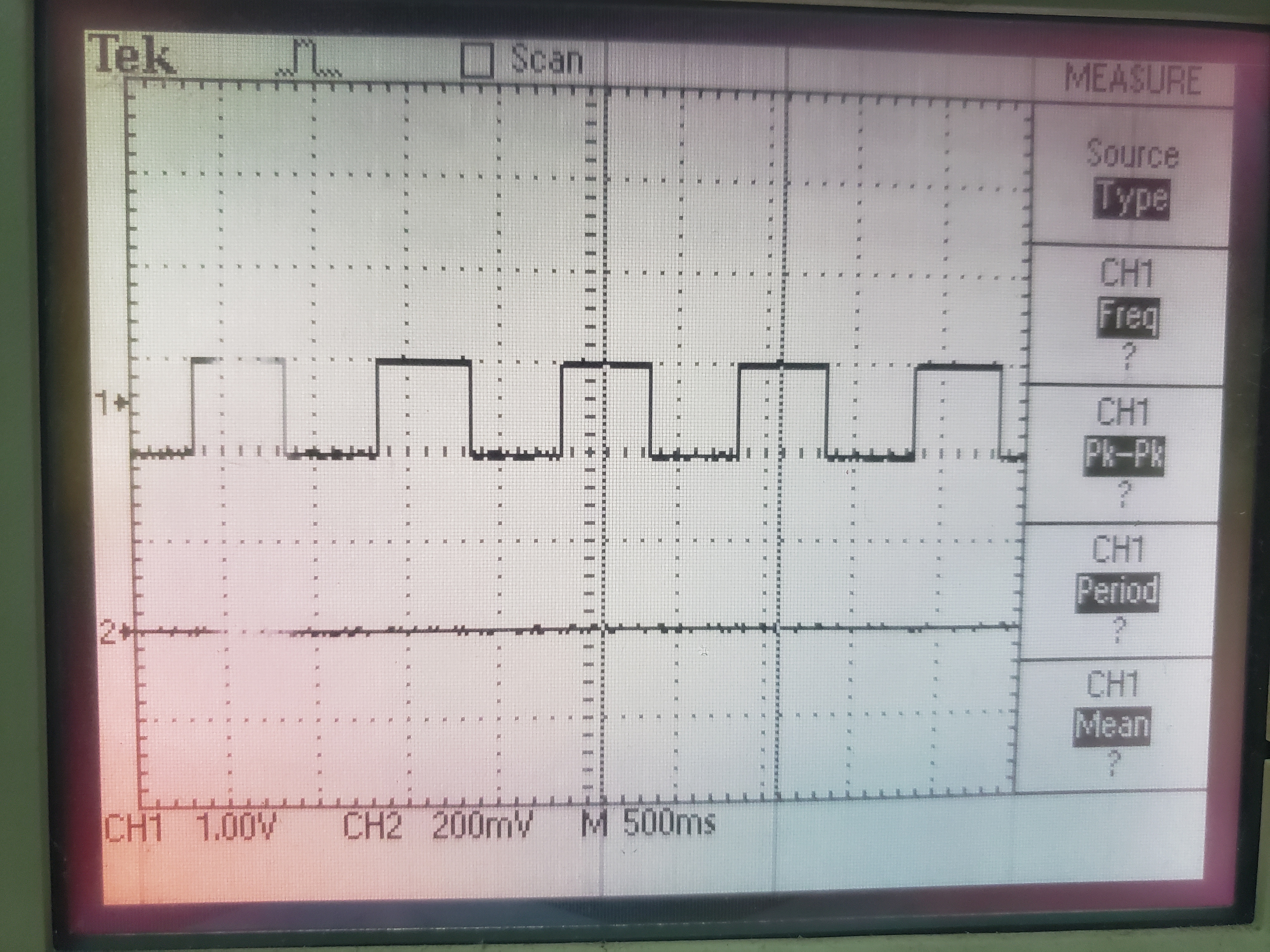
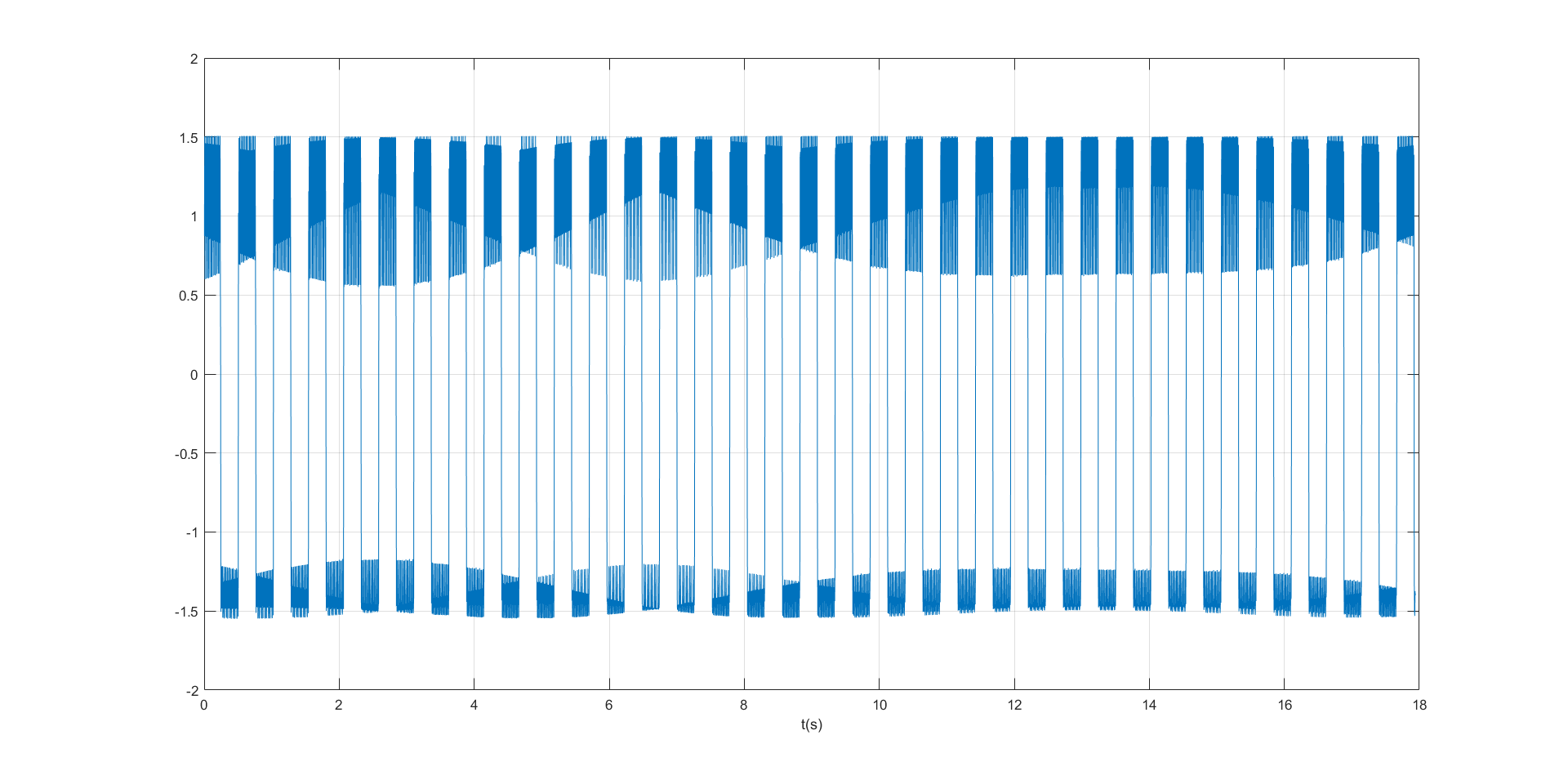
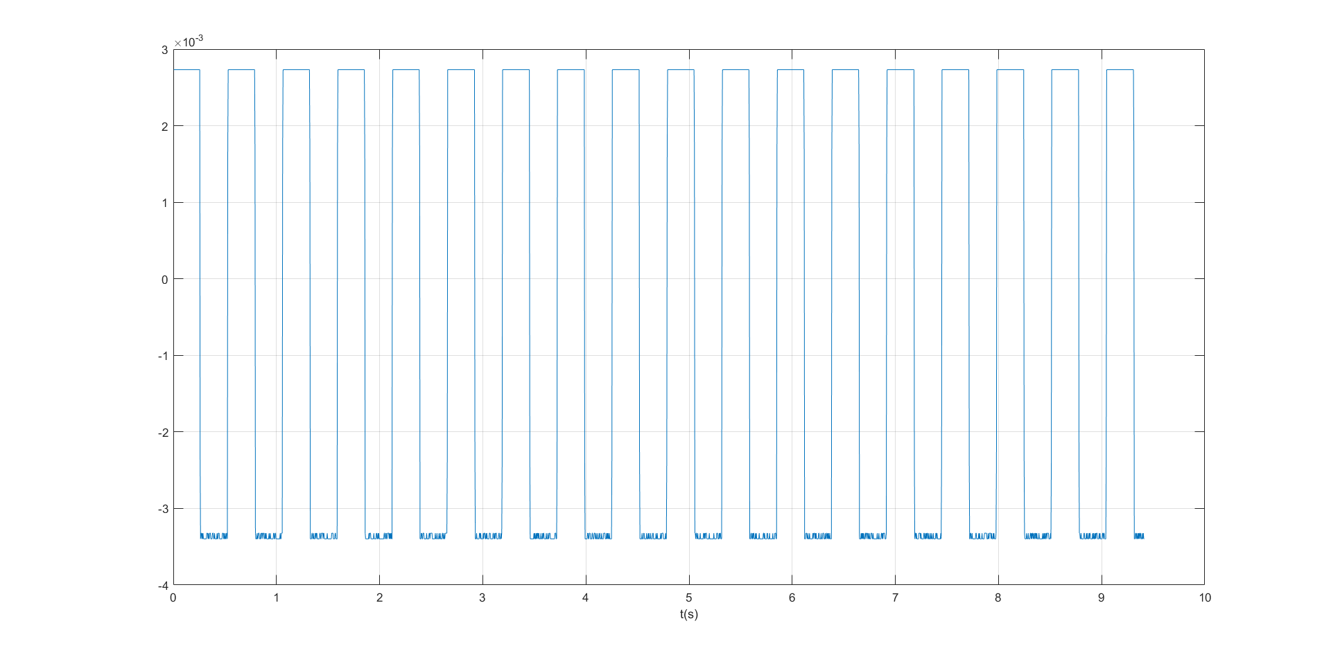
    3. I also tried to test the square signal. I send the the 0x4200A3, 0x440005 and 0x450005 to the chip, and I got this:

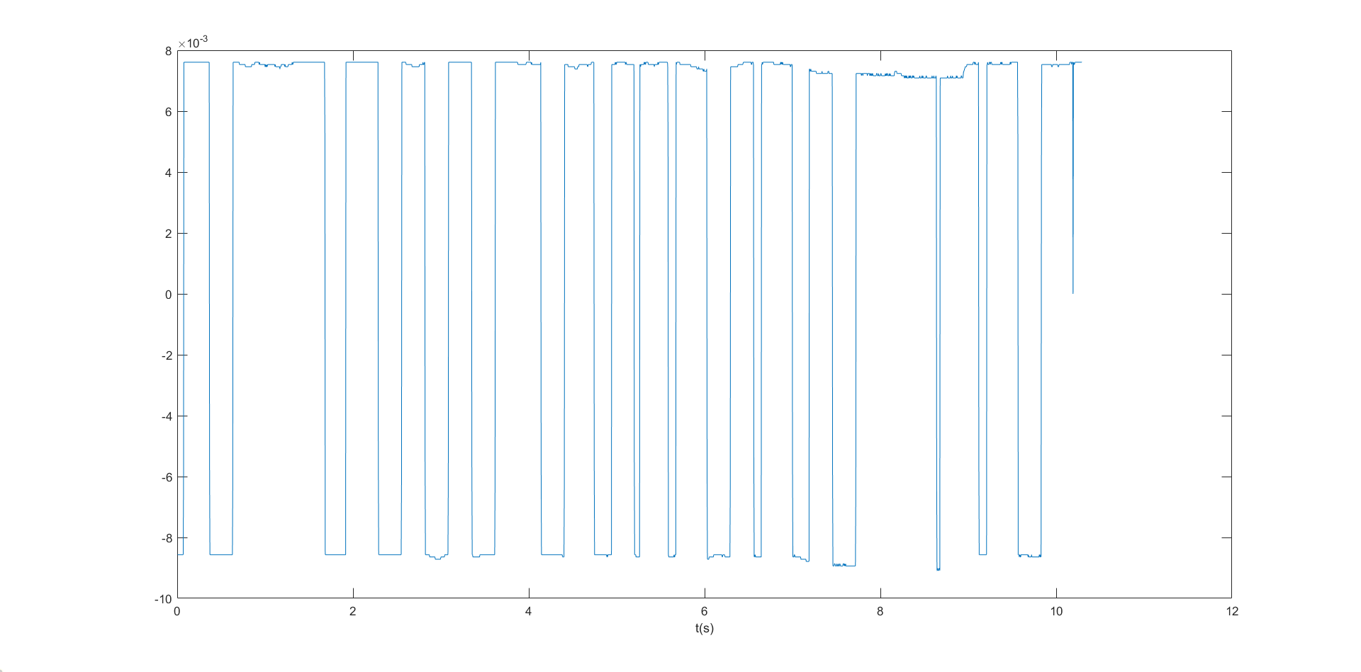
    The first is getting from channel 1, and the second is getting from channel 2.

    I just test the square signal only once because when I want to do the test again, I met the situation I discribed in the first question. I cannot start reading data after sending START and RDATAC. I also tried to get the START pin high, but it didn't work neither.

    I hope someone could tell me where my issue could be.

Thanks so much,

Yuhang.


  • Hi Yuhang,

    More than likely there is something small going wrong in the configuration of the device. 

    Please see the SPI communication post, review your power-up flow, confirm that the device is working using the BIOFAQ: https://e2e.ti.com/support/data-converters/f/73/p/772058/2855202

  • Hi Alexander,

    Thanks for your help.

    Now I can handle the issue which is failing to read data continuely.

    Unfortunately, however, I still got some other problems like what I discribed before.

    The first is that I cannot got the right ECG when acquiring from myself. There is a lot of noise in it even if I applied the RLD.  I write the 0x38 to both CH1SET and CH2SET. Do I configure the registers correctly? I did't seperate the DGND and AVSS independently, I just have one GND. Could it be the reason that I got a lot of noise?

    The second is that I got the wrong frequency when acquiring a square signal of 1Hz generated from a signal generator. Here is the result I got in 
    oscilloscope and the ADS1292R:

    But when I test it by generating 1Hz square signal from the ADS1292R, I got the right result through both 2 channels:

    I beg your further help.

    Yuhang.

  • Hi Yuhang,

    You will want to us 0x30 for Ch1Set and Ch2Set. 0x38 connects RLD_DRPM (both positive and negative inputs are connected to RLDIN).

    Using 1 GND shouldn't be an issue as long as the board is laid out well, but it is possible that this is the issue. Do any of your analog traces cross digital signal lines? Please post your PCB layout and schematic for me to take a look at. 

    Are you using unipolar or bipolar power supplies? In your first post it says 3.3V, which means the bipolar square wave you're applying to the inputs may be outside the common-mode range of the input. Is this oscilloscope picture from the output of the signal generator or the input pins of the device? 

  • Hi Alexander,

    I was a little confused about the RLD configuration. If I want to apply the RLD, after writing 0x30 for Ch1Set and Ch2Set, should I write the bits[3:0] of RLD_SENS?

    I didn't let my analog traces cross the digital signal lines, here are my PCB layout and schematic:

    I'm using unipolar power supply. Afraid of insufficient power supply, I apply 3.3V to DVDD too.

    In my last reply, the oscilloscope picture is from the output of the signal generator and the second picture is the result when apply that signal to ADS1292R.

    I tried write 0x30 to Ch1Set and Ch2Set, and I got the right signal of myself, but I don't have any idea about the big noise of the latter part of my signal:

  • Hi Yuhang,

    Take a look at figure 47. in the datasheet. I would write to bits[3:0] of RLD_SENS, but try experimenting and see which combination of channels to derive gives the best result. I would start with IN2P and IN2N. 

    Schematic looks good. PCB looks ok. There are some analog lines crossing each other, traces go through vias, and it looks like VCC crosses LA. This is not ideal. I would recommend attaching some small wires directly to the input pins of the device and measuring with an oscilloscope to see what exactly is reaching the input of the device. Does it look exactly like the output from the signal generator or is there some extra noise added? 

    The noise at the end of the measurement is probably due to movement, and/or the electrode connection degrading (not sticking as well). All in all, looks pretty good to me. 

  • Hi Alex,

    Thank you so much for helping me these days!

    Best wishes,

    Yuhang

  • Hi Yuhang,

    You're most welcome! 

    Good luck,