This thread has been locked.

If you have a related question, please click the "Ask a related question" button in the top right corner. The newly created question will be automatically linked to this question.

ADS124S08: Problems with accuracy measurement of PT100 sensors

Part Number: ADS124S08

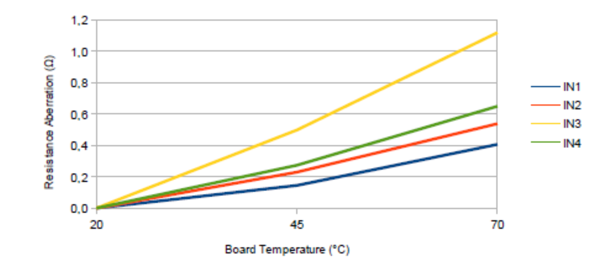
During the tests we found temperature dependence of resistance measurement of PT100 sensors connected to inputs ADS124S08IPBSR.
Finally, we did a test where the PCB with ADS124S08 was inside the climate chamber and the PT100 sensors outside.
Below are the measurement results. The inputs use very precise resistors with a tolerance of 0.1%.
Do you have any idea where we could make a mistake?

Kind Regards,

Tom

  • Measured results:

  • Hi Tomas,

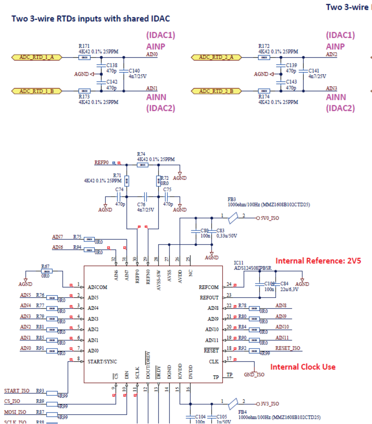
    Welcome to the E2E forum!  Consider that not only does the initial accuracy matter with the values of resistance but so does the drift performance.  A 25ppm per deg C drift amounts to about 5.5 Ohms over 50 deg C.  This drift of the reference resistor will directly impact the result by about 1%.  Now this would only be part of the error you are seeing.  It is not clear to me how you are providing the IDAC current to the RTD.  Can you give me more detail on the current path from the ADS124S08 to the RTD and back to the reference resistor?  Can you also send me the register settings you are using?

    As well as the drift of the resistors is drift of the IDAC sources and how well they match.  Taking 2 measurements with swapping the IDAC sources and averaging the two results can help reduce the error.

    Make sure you have reviewed this RTD guide for additional help (IDAC current chopping is discussed in section 1.4.2):

    http://www.ti.com/lit/an/sbaa275/sbaa275.pdf

    Best regards,

    Bob B

  • Hi Bob,

    Colleagues let me know more details about this trouble.
    Please see below,
    Tomas

    xxxxxxxxxxxxxxxxxxxxxxxxxxxxxxxxxxxxxxxxxxxxxxxxxxxx

    We measure only active RTD (3-wire):
    RTD#1 [AN0, AN1]
    RTD#2 [AN2, AN3]
    RTD#3 [AN5, AN6]
    RTD#3 [AN9, AN10]

    - we use internal IDAC1 and IDAC2 connected to the given ANx for particular RTDx as current sources for RTDx
    - the principle of measurement is used according to www.ti.com/.../sbaa275.pdf chapter "2.3 Three-Wire RTD Measurement, Low-Side Reference"
    - Polynomial approximation (ITS-90) is used to convert from measured resistance to temperature, but this is just mathematics

    /****************************************************************************************/
    /** RTD Chnannel configuration

        // RTD#1
        case PKG_ADS124S08_CH_RTD_0_1:
        {
          sRegINPMUX.uContent.bits.bMuxP = 0;
          sRegINPMUX.uContent.bits.bMuxN = 1;
          ads124s08_WriteReg(sRegINPMUX.bAddr, &(sRegINPMUX.uContent.bValue), 1);

          sRegIDACMUX.uContent.bits.bI1Mux = 0;
          sRegIDACMUX.uContent.bits.bI2Mux = 1;
          ads124s08_WriteReg(sRegIDACMUX.bAddr, &(sRegIDACMUX.uContent.bValue), 1);

          break;
        }

        // RTD#2
        case PKG_ADS124S08_CH_RTD_2_3:
        {
          sRegINPMUX.uContent.bits.bMuxP = 2;
          sRegINPMUX.uContent.bits.bMuxN = 3;
          ads124s08_WriteReg(sRegINPMUX.bAddr, &(sRegINPMUX.uContent.bValue), 1);

          sRegIDACMUX.uContent.bits.bI1Mux = 2;
          sRegIDACMUX.uContent.bits.bI2Mux = 3;
          ads124s08_WriteReg(sRegIDACMUX.bAddr, &(sRegIDACMUX.uContent.bValue), 1);

          break;
        }

        // RTD#3
        case PKG_ADS124S08_CH_RTD_5_6:
        {
          sRegINPMUX.uContent.bits.bMuxP = 5;
          sRegINPMUX.uContent.bits.bMuxN = 6;
          ads124s08_WriteReg(sRegINPMUX.bAddr, &(sRegINPMUX.uContent.bValue), 1);

          sRegIDACMUX.uContent.bits.bI1Mux = 5;//4;
          sRegIDACMUX.uContent.bits.bI2Mux = 6;//7;
          ads124s08_WriteReg(sRegIDACMUX.bAddr, &(sRegIDACMUX.uContent.bValue), 1);

          break;
        }

        // RTD#4
        case PKG_ADS124S08_CH_RTD_9_10:
        {
          sRegINPMUX.uContent.bits.bMuxP = 9;
          sRegINPMUX.uContent.bits.bMuxN = 10;
          ads124s08_WriteReg(sRegINPMUX.bAddr, &(sRegINPMUX.uContent.bValue), 1);

          sRegIDACMUX.uContent.bits.bI1Mux = 9;//8;
          sRegIDACMUX.uContent.bits.bI2Mux = 10;//11;
          ads124s08_WriteReg(sRegIDACMUX.bAddr, &(sRegIDACMUX.uContent.bValue), 1);

          break;
        }
    /****************************************************************************************/

    /****************************************************************************************/
    /** Common configuration for ALL RTDx

    /// Enable the PGA set the GAIN
      sRegPGA.uContent.bits.bDelay = 3;         // 256 x tMCO
      sRegPGA.uContent.bits.bGain = bGainExp;
      sRegPGA.uContent.bits.bPgaEn = 1;         // Enable
      ads124s08_WriteReg(sRegPGA.bAddr, &(sRegPGA.uContent.bValue), 1);

      /// Global Chop Disable, Conversion mode SINGLE shot, 10 SPS, Low-Latency filter On
      sRegDATARATE.uContent.bits.bGChop = 1;
      sRegDATARATE.uContent.bits.bMode = 1;

      sRegDATARATE.uContent.bits.bDR = 2;   //10 SPS
      //sRegDATARATE.uContent.bits.bDR = 4;   //20 SPS
      //sRegDATARATE.uContent.bits.bDR = 7;   //100 SPS

      sRegDATARATE.uContent.bits.bFilter = 1;
      ads124s08_WriteReg(sRegDATARATE.bAddr, &(sRegDATARATE.uContent.bValue), 1);

      /// Voltage reference - internal reference always on, reference input REFP0/REFN0,
      ///                     reference buffers REFPx enabled, REFNx disabled
      ///                     FL_REF_L0 anbled, FL_REF_L1 disabled
      sRegREF.uContent.bits.bRefCon = 2;
      sRegREF.uContent.bits.bRefSel = 0;
      sRegREF.uContent.bits.bRefPBuf = 1;
      sRegREF.uContent.bits.bRefNBuf = 0;
      sRegREF.uContent.bits.bFlRefEn = 1;
      ads124s08_WriteReg(sRegREF.bAddr, &(sRegREF.uContent.bValue), 1);

      /// Set On excitation current with
      sRegIDACMAG.uContent.bits.bFlRailEn = 1;
      sRegIDACMAG.uContent.bits.bPsw = 1;

      sRegIDACMAG.uContent.bits.bIMag = 4;  // 250uA
    //  sRegIDACMAG.uContent.bits.bIMag = 5;  // 500uA
    //  sRegIDACMAG.uContent.bits.bIMag = 6;  // 750uA
    //  sRegIDACMAG.uContent.bits.bIMag = 7;  // 1000uA
    //  sRegIDACMAG.uContent.bits.bIMag = 8;  // 1500uA
    //  sRegIDACMAG.uContent.bits.bIMag = 9;  // 2000uA

      ads124s08_WriteReg(sRegIDACMAG.bAddr, &(sRegIDACMAG.uContent.bValue), 1);
    /****************************************************************************************/

  • Hi Tomas,

    Thanks for the additional information.  If you look closely at the circuit shown in Figure 9 of section 2.3 of the referenced document you will notice that the IDAC current flows from a different pin than the measurement pins.  This is to eliminate any error from both initial accuracy and drift of the filter resistors as well as the IDAC sources mismatch.  In your circuit the current is flowing through the filter resistors (R171 and R173 for example).

    In an ideal condition where there is no drift or accuracy issues, the voltage drop across each resistor would be the same and would cancel from the conversion result.  However, this isn't what happens as there is no guarantee the resistors will drift the same value and for sure there will be some mismatch of the IDAC sources. 

    There are several possible options.  One is to try IDAC chopping and another is to reduce the value of the filter resistors so that any potential error from the resistors is minimized.  A much better approach would be to route the current around the filter resistors directly to the RTD.  This would require using one set of  AIN inputs to be used solely for the IDACs and then run the IDAC current through a mux to route to the desired RTD when the measurement is to take place.

    Best regards,

    Bob B

  • Hi Bob,

    many thanks for yours initiatives, for our better results of resistance mesurement.

    We has also designed a two last channels with possibility use external IDACs

    where we have a possibility test a your recommendation mentioned above (external IDACs with its CHOPPING).

    Please tell me which values of serial resistors are appropriate use?

    R74 = ? (stay same)

    R71 = ?

    R90, R91, R100, R101 = 0R0

    R94, R95, R98, R99 = ? 

    Many thanks, for yours replies

    Milan 

  • Hi Milan,

    Welcome to the E2E forum! Let's discuss IDAC chopping with your original circuit question.  IDAC chopping will help reduce the error of the IDAC mismatch, but it will not reduce the temperature coefficient error of the resistor drift.  The drift error for these 25ppm per deg C resistors can be upwards of 5 Ohms.

    So your options are to bypass the input filter resistors so that the IDAC current doesn't flow through them. Another option is to use a much lower value of resistance so that the effect is minimized to a lower voltage drop differential across the filter resistors.  A third option is to use a more stable resistor such as 5ppm or 10ppm temperature coefficient.  What you choose to do depends on the precision required for your system.

    There is still the temperature coefficient issue with the reference resistor (R74).  This will also add error at about 0.1% for the temperature range used.  Here again the error can be reduced by using a 5ppm or 10ppm resistor, but here you need to do some research and cost can vary considerably.  To get a 10ppm resistor you may find it much less expensive to find a value that is slightly different than the value you are now using.

    R71 does not need to change, nor does R94, R95, R98 or R99.

    Best regards,

    Bob B