This thread has been locked.

If you have a related question, please click the "Ask a related question" button in the top right corner. The newly created question will be automatically linked to this question.

DAC161P997: output

Expert 1730 points
Part Number: DAC161P997

Hello,

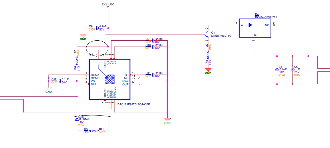
     Following is our circuit diagram:

 Iout is connected to a 330E resistor followed by the ground terminal of a bench top DC supply configured for 24V and current limit set to 40mA, while the positive of the DC supply is connected back to D4 in the schematic. 

The problem is as follows: 

1) When the device is powered ON, the current in the loop is ~3.4mA (calculated by the voltage drop across the 330E resistor). 

2) When a current value is set (we tried a few values like 0x2AAA, 0x9C40, 0xEA60) the output current changes to the set value for 100ms and then goes back to 3.4mA. 

3) This time duration coincidentally matches the Timeout Period (TM) mentioned in the datasheet. 

4) We do not have the provision to read back any data or error messages that might be issued by the device. 

5) Also, we do not see the current changing for all values between 10000 and 65000 (for ex. the current doesnt change for 30000). 

Please advise on where could the issue be. Thank you for your help in advance,

  • P.S.

    The 3.4mA current (upon power ON and after the 100ms current change) is equal to the ERR_LOW value (0x2400). This probably indicates ERRLVL = LOW condition. Also, the power up current is equal to this value (IERRL). 

    This implies the following in our opinion:

    1) The power up current is correct (equal to IERRL)

    2) When a DAC value is set, the value changes to the set value (for the few values that we tried) for the duration of TM and then goes to IERRL again indicating a fault/error of some kind. 

    Looking forward to your inputs,

  • Hi SM,

    I'll take a look at this on Monday, but for starters, please verify that you supply is 'floating' in respect to the DAC161's ground pin. Consider that the IOUT- node needs to be a lower potential than the ground node of the DAC. so for example if the ground of the DAC is connected to the ground of the power supply, then the DAC cannot really force a current.

    Thanks,

    Paul

  • HI Paul,

          Thank you very much for helping out on a Saturday. I think the grounds are floating with respect to each other because when we tried shorting them the 3.4mA dropped to zero.

    Looking forward to your inputs, have a good Sunday.

    Regards,

  • Hi SM,

    I wonder if you are just seeing the inactivity alarm.  Try clearing the config2.CHANNEL bit to disable that.  

    Thanks,

    Paul

  • Hello Paul,

               We used the code provided by TI and there is some improvement. 

    The DAC word is being sent continuously to get the current output (we are getting the correct current) which means that our controller cannot do other things. Please advise on how to configure the DAC for a particular current and then the DAC should maintain that until the next change. 

    Regards,

  • Hi SM,

    You can set the SWIF to be inactive be sending the "L" command.

    Thanks,

    Paul

  • Hi Paul,

           Will the L command have to be sent every time a new DAC word is sent?

    I suppose it has to be sent immediately after the DAC word otherwise the output would go to the IERRL state.

    I think this might work. Will try and update you tomorrow.

    Regards,

  • Hi Paul,'L' symbol is basically LOW for 1 complete duty cycle. After payload (DAC word)we are sending 'D'(to complete a frame) which is HIGH for half duty cycle and LOW for half cycle . So wouldn't it be the same as not sending something .

  • Hi Kishore,

    My suggestion is to send an 'L' after the 'D' to suspend the transmission - is that not working?

  • Hello Paul,

              Thank you for your help. It works now.

    Regards,