This thread has been locked.

If you have a related question, please click the "Ask a related question" button in the top right corner. The newly created question will be automatically linked to this question.

ADS1298: Full-scale issue

Part Number: ADS1298

Hi.

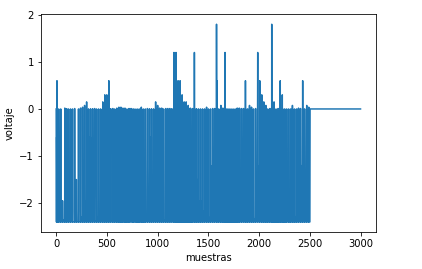
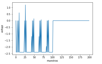
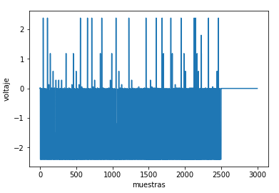
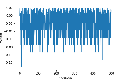
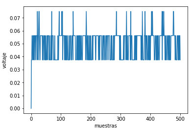
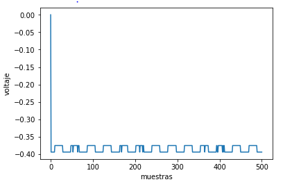
I've been struggling with some issues related with full-scale range, since i recieve data from the ADS1298 with values of 0x7fffff and 0x800000, i thing my device is saturating and i don´t  know how to fix it.

I'm interfacing the ADS1298 with a STM32F407. The device is supplied with AVDD= 2.5v and AVSS=-2.5v and DVDD=3.3v. i've used the "How do I convert ADC output codes to volts?" forum as a guide but with no luck, my data retrieval is always 0x7fffff or 0x80000, no matter if i'm connected or a test signal or  simply capting the enviroment, never chages the data.

My registers are configured as follow:

Reg0x01=0x06
Reg0x02=0x20
Reg0x03=0xCC
Reg0x05=0x60
Reg0x06=0x60
Reg0x07=0x60
Reg0x08=0x60
Reg0x14=0x00
Reg0x17=0x08
Reg0x18=0x08
Reg0x19=0xD4

the other registers i don't use them.

Don't know if it's software or hardware issue. 

Somebody please help me, i've been stuck with that long time ago.

  • Hi Carlos,

    What is your input signal?

    What is your reference voltage? 

    What is the PGA gain setting? 

    Please see section 9.3.1.4 Analog Input of the datasheet. 

  • Hi Alexander, thanks for your reply.

    Input signal = i've tried with the internal test signal and connecting myself to the device to get my heart signal. The results are the same. 

    My VREFP = 2.4v, i don't know if i have to change the VREF_4V bit of the config3 register, and set it to 1. 

    My VREFN =-2.5v

    PGA gain per channel = 12

  • Hi Carlos,

    Can you confirm that the device is still functional using the BIOFAQ?

    Can you show scope shots of your digital communication? MISO, MOSI, CS, START?

  • Hi Alexander.

    The device allows to write and read the Registers, i can read back what i write to each register. 

    I can Read the ID register, and the voltages of  VCAPs seem to agree with the values of the BIOFAQ.  


    MISO is connected to DOUT

    MOSI is connected to DIN

    CS is a selected pin by me, i reset the pin and set it manually 

    Start is no connected so a i can issue the command as needed 

    Communication.docx

  • Hi Carlos,

    Is it possible to see oscilloscope screenshots of your communication? 

    Does the result change if a gain of 1 is used instead of 12? 

    Can you provide the schematic and pictures of PCB layout? 

  • Hey.

    unfortunably i have no oscilloscope in here. I debug the MCU step by step and i see directly what is the device is giving back.

    with gain 1 i recieve the same data. 0x7fffff and 0x800000.

    here is the schematic i'm using for the regulators and the ADS1298.

    Esquemas.pdf

  • Hi Carlos,

    Got it. For now, do not configure WCT, and other miscellaneous registers. I recommend only enabling the internal reference and necessary input channels to debug, leave all other registers default and see if that helps. 

    If the device ID is being returned correctly, the power supplies should be powering up correctly. Since changing the gain or input signal does not affect the full-scale result, that shouldn't be the issue. That means it either has to be something with the reference being mis-configured, or an error in the code. 

    The schematic for the reference looks fine, but if possible confirm on the PCB that the capacitors are correctly routed and going to the pins. 

    If you can somehow get access to an oscilloscope, that would be great because then we can confirm that the device is outputting data correctly and it is an error with the code.  

    Let me know. 

  • Alexander,

    I've configurated the nexts registers as follow, the other registers are configurated by default by the device.  

    Reg Config3 = 0x80 only enable the internal reference buffer
    RegCH1Set = 0x10 only enable the firt channel with a gain of 1 

    I connect myself to the device and i get sometimes only 0x7ffff back and sometimes only 0x80000 but no different values, so i tried  leaving  the cable on the air just capting the enviroment to see if changes anything, but no. I don't have a singal generator to try out with a known signal, so i don't really know how else i can try. 

    Don't know if it's a code error but this is how i'm converting data to voltage, as i've seen in the "How do I convert ADC output codes to volts?" forum.

    it's in Python so...

     import serial

    import numpy as np

    from matplotlib import pyplot as plt

    dato=np.zeros(3000)

    contador=1

    puerto = serial.Serial('COM3',230400, timeout=1)

    VREF= 2.5

    GAIN= 1  

    MSB= 0x800000

    Samples=int(input('ingrese numero de muestras a graficar\n Muestras= '))

    LSB=((2*VREF)/GAIN)/(2**23)

    while contador<=samples:

        ch = puerto.read(3)

        valordato=ch[0]<<16 or ch[1]<<8 or ch[2]

        datoMSB = valordato & MSB

        if datoMSB == 0:

            data=valordato*LSB

        else:

            data=((2**24)-valordato)*LSB

        dato[contador]=data

        contador+=1

  • Hi Carlos,

    Can you measure between VREFP and VREFN? 

    In you previous post it looks like the difference is actually 4.9V?

    I'm not sure if this is Python language or not, but the " ** " in LSB=((2*VREF)/GAIN)/(2**23) and  data=((2**24)-valordato)*LSB should be to the power of " ^ ".

    LSB should also be LSB = (2 x VREF)/ Gain / (2^24 - 1). Notice that 1 is not subtracted from the exponent 24. 

    valordato is the decimal equivalent of the number, correct?

     data=((2**24)-valordato)*LSB should be  data=(valordato-(2**24))*LSB

  • Hi Carlos, 

    Any luck? 

  • Hi Alexander,

    Yes, in python the "^" operator is represented by "**".

    Notice that i substract the -1 on the equation since the beginning LSB=((2*VREF)/GAIN)/(2**23) as the exponent is not 24-1 but 23, in any case i'll put it following your suggestions. so it'll be  LSB = (2 *VREF)/ GAIN / (2**24 - 1).

    Correct, valordato is the 24 bit channel data that i recieve from the device. 

    OH ok! i corrected that so the data equation is now data=(valordato-(2**24))*LSB. 

    The problem  still that i'm only getting either 0x80000 the most part or 0x7ffff some times from the ADS1298,  no other values. 

    I've changed the programming, instead of sending the RDATA command i'm using the  RDATAC   following the  figure 93 of the datasheet, and it sends different values not only 0x7fffff nor 0x80000, but i'm not sure if it's working the proper way, since i'm getting as test signal this.... 

    (similar in each channel)

    (similar in each channel)  this with more samples.

    (similar in each channel) and this when i connect myself.

    i don't really see what i want to see on this. I'm sampling 500 SPS and it doesn't show what it supposed to the square signal on the Test and the heart signal with noise or something, so i don't know. 

  • Hi Carlos,

    You are getting closer! 

    Remember your order of operations and PEMDAS. Exponents (2^24) are processed before Subtraction. So for (2^24-1), it is really ((2^24)-1). 

    Few other things... do not write 0x80 to CONFIG3. This is invalid, see page 69 for details, but notice that the second bit must be 1. Instead of 0x80, write 0xC0. 

    Additionally, see that the reference voltage is actually 2.4V, not 2.5V as written in your code. This will return an invalid LSB size. 

    After making these changes, can you return your LSB size just so we can confirm that it is being calculated by the program correctly? 

  • Hi Alexander, 

    Ok i had no idea it was ((2^24)-1). i've all ready changed it. 

    i've measured the voltages with this results.

    VREFP=1.4v 

    VREFN=-2.3v

    so VREF= 3.7v  (Note: internal buffer is enable)

    VCAP1 = -1.1

    VCAP2 = 0.4v

    VCAP3 = 4.4v

    VCAP4 = 1.4v

    I've set the VREF_4V bit on the Config3 to 0 so the VREF is set to 2.4, however, the voltage in the hardware is one volt down as i mentioned above. 

    is this the problem? 

  • Hi Carlos,

    This could certainly be the issue. Is it possible that the device was damaged when installing or debugging? 

    Was this soldered in by hand or at a board house? 

    You may want to try replacing the device to see if that helps. 

  • Hi Alexander, 

    That certainly are really bad news, since is not the first device damaged in my attempt to run this project.  

    it was soldered by hand by me actually, but i was as  carefully i could. 

    is there a way where i can lift those voltages without replacing the device? i mean, i think it is no damaged because it lets me read and write reagisters and ID. And im connecting th devices as you noticed posts above. So, is there anything i could do to enhance this voltages issue? 

  • Hi Carlos,

    It could be that just the reference buffer is damaged. You could perhaps try wiring in an external reference. 

    The last possibility is that there is some error during power-up such that the reference is not being configured correctly. However I don't believe this to be the issue since the ID is returning correctly. 

    Try to use an ESD strap and magnification tool if possible. 

  • Hi Alexander, 

    I've achieved to lift the VREFP voltage so now that pin is 2.4 and the VREF=4.7v. 

    When i put the test signals i get this result:

    channel 1

    channel2

    Channel3

    Certainly it has been a progress since i've lifted that voltage. Channel one seems to be failling but i dont now why, it could be damaged?, the second channel ilustrates the square test signal with noise, i guess its working?, and the third one is the best signal of all, this could have solved that. Nontheless, when i connect my self i still don't get the signal that i want for the device.

    this is the code in python to get and convert data to voltage. 

    VREF= 2.4
    GAIN= 1
    MSB= 0x800000
    muestras=int(input('ingrese numero de muestras a graficar\n Muestras= '))

    LSB=((2*VREF)/GAIN)/((2**24)-1)

    while contador<=muestras:

    ch = puerto.read(3)
    valordato = (ch[0] << 16) or (ch[1] << 8) or ch[2]
    datoMSB = valordato & MSB

    if datoMSB == 0:
         data=valordato*LSB
    else:
         data=(valordato-(2**24))*LSB
    dato[contador]=data
    contador+=1

    And this is how i'm configurating ADS1298

    Reg0x01=0x86
    Reg0x02=0x00
    Reg0x03=0x40 (External reference)
    Reg0x05=0x10
    Reg0x06=0x10
    Reg0x07=0x10
    Reg0x08=0x10
    Reg0x14=0x00
    Reg0x17=0x08
    Reg0x18=0x08
    Reg0x19=0xD4

  • Hi Carlos,

    At this point it's hard to say exactly what is happening without the proper equipment to debug. I'm happy that you have been able to make progress, and perhaps there is more to be made. I recommend looking very closely at your solder connections and continuing to debug. Let me know if you have specific questions or concerns about the device.