This thread has been locked.

If you have a related question, please click the "Ask a related question" button in the top right corner. The newly created question will be automatically linked to this question.

TSW1400EVM: Parallel TSW1400 data capture with ADS52J90 ADCs

Part Number: TSW1400EVM

Hi,


We have some questions relating to use of the ADS52J90 ADC with the TSW1400 data capture board.  We are intending to use these parts in an ongoing client-funded project.

We are hoping to confirm selection of the AD552J90 for the design and to place an order for multiple TSW1400 boards as soon as possible, but we first just need to confirm our understanding of their operation and capabilities.


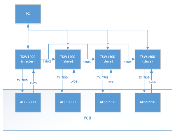
  • We would like to capture data from four ADS52J90 ADCs.  Each ADC will be connected to a separate TSW1400 data capture board
  • The four ADCs will be mounted on our own PCB (together with the associated analogue circuitry)
  • We need to capture data from all four ADCs simultaneously
  • Our proposed configuration is shown in the diagram below:


Our questions are as follows:


  1. From page 30 of the TSW1400 user manual SLWU079D, we can see that it appears to be possible to use up to five TSW1400 data capture boards to capture data in parallel using one board as the ‘master’ and connecting each of the SYNC1, SYNC2, SYNC3 and SYNC4 outputs from the master board to the EXT_TRG_INPUT of a ‘slave’ board. Can you confirm that it would be possible to capture 1000 samples from four ADS52J90 ADCs (i.e. one master and three slaves) at the same time using this setup?
  2. Does each TSW1400 board also provide the TX_TRIG input to the connected ADC, or must we provide a separate source to drive the ADC TX_TRIG signal inputs?
  3. Are we correct in thinking that the ADC samples the input continuously, and the TSW1400 only captures the data when triggered?
  4. On the ADS52J90 eval board, there appear to be 3 different possible sources of the TX_TRIG signal into the ADC – either from an external source through an SMA connector, from the USB-UART converter or from the FPGA on the TSW1400 data capture board. For our application, should we take the TX_TRIG signal from the TSW1400 data capture board, or somewhere else?
  5. Is it possible to use the MATLAB automation described in SLAA752 to automate the capture of data from the four TSW1400s, so that all four capture data that was sampled at the same time, as we require?
  6. If it is possible to use MATLAB as above, how will that work?  For example, will one board be the master and trigger the other boards to capture the data?  Can the PC then connect with each TSW1400 in turn to download its data, and then return to the master board to trigger the next data capture?
  7. The setup above assumes that we will use a PC to initiate the data capture. Is it possible to instead send an externally generated hardware trigger signal to the four TSW1400 boards to capture the data and then transfer the data from each one to the PC some time after?


If anything is unclear, or you need any further information, please let me know.

  • Hi,

    From our group we were testing using one ADS52J90EVM and one TSW1400EVM only.

    We didn't connect four TSW boards before.

    and we don't think we can support that.

    Thank you!

    Best regards,

    Chen 

  • Hi Chen,

    Page 30 of the TSW1400 user manual states that:

    "Master and slave triggering modes are available for the TSW1400. Under 'Data Capture Option' there is now a 'Trigger Option' menu with two sub-options. 'Trigger Mode Enable' allows externally triggering capture into DDR memory through SMA connector named 'EXT_TRG_IN' while 'Software Trigger' generates a trigger on the four SMA connectors labeled 'SYNC' "

    The process of triggering data capture for multiple TSW1400 boards is also described on pages 16-20 of the HSDC Pro GUI manual (SLWU087D)

    Your response seems to contradict the information described above, perhaps you could explain? It would be great if you could put me in touch with a design engineer to discuss this!

    Thanks

    Henry

  • Hi Henry,

    We will look into your detail information

    and will reply to you very soon.

    Thank you!

    Best regards,

    Chen

  • Hi Henry,

    Thanks for using ADS52J90 devices.

    First for your concern about the more details how to use multiple TSW EVMs,

    please contact with TSW EVM groups.

    And for your concern about how to build a new PCB board for ADS52J90 devices (on one PCB board, right?)

    with TSW1400EVM boards, you need to know:

    1) for Hardware wise (master):

    Please notice:

    SYNC1 needs to connect to TSW1400_EXT_TRIG_INPUT_#1 and ADS52J90_TX_TRIG_#1

    SYNC2 needs to connect to TSW1400_EXT_TRIG_INPUT_#2 and ADS52J90_TX_TRIG_#2

    SYNC3 needs to connect to TSW1400_EXT_TRIG_INPUT_#3 and ADS52J90_TX_TRIG_#3

    SYNC4 needs to connect to TSW1400_EXT_TRIG_INPUT_#4 and ADS52J90_TX_TRIG_#4

    2) for Software wise

    a) since our TSW1400 GUI can only recognize its own ADS52J90 (on one EVM)

    b) and one TSW1400 GUI can only turn-on used for running one ADS52J90 device

    Therefore, you have to make the new program GUI to run your 4 TSW1400EVMs at a time.

    3) also for your other concerns,

    Automation using tools like C, Matlab and python is also supported.
    Please refer to the Automation DLL manual and examples that would be located in the HSDC Pro Installation directory:

    “C:\Program Files (x86)\Texas Instruments\High Speed Data Converter Pro\HSDCPro Automation DLL\Manual and Examples”

    Thank you very much!

    Best regards,

    Chen


  • Hi Chen,

    You say to contact TSW EVM groups, how do I do this?

    Thanks

    Henry

  • Henry,

    I am checking with the software team regarding these TSw1400 questions.

    Regards,

    Jim

  • Hi Jim,

    Thank you, could I also ask a few additional questions?

    8. Is there a minimum sample clock frequency for the ADS52J90? I am finding that using sample clocks below about 2.03 MHz the TSW1400EVM is unable to receive data from the ADS52J90EVM. I have looked at the LVDS bit clock coming from the ADC and it appears as a regular clock pulse above 2.03 MHz, but below this frequency the pulse widths appear to become variable and inconsistent which is presumably causing the problem, what would be causing this?

    9. I would ideally like to be able to capture several smaller captures using the TSW1400EVM - e.g. trigger data capture of 100 samples 20 times before downloading all 2000 samples from the TSW1400 to the PC. I need a lot of short captures so it will be inconvenient to have to transfer the data to the PC after every triggered capture. Is there any way to do this?

    10. I notice that data transfer from the TSW1400EVM seems to become increasingly unreliable as the number of samples captured increases - for example, it captures the default 65536 samples with no problem, and the same for 655360 ​samples, but if I try to capture 6553600 samples, it occasionally works, but usually throws up a Read DDR to file TIMED_OUT_ERROR. Why would capturing more samples cause this error?

    11. If I try to capture a full memory of data from the TSW1400 (512M samples) the data downloads over about 20 minutes but at the end I get an error that the PC does not have enough memory and the program crashes? The RAM in the PC does not appear to be excessively full by the end of the data capture, if this is the problem then how much RAM would the PC need in order to reliably download all 512M samples from the TSW1400? If the problem is caused by the HSDC Pro GUI attempting to do some processing (e.g. FFT) on the captured data, is there any way to bypass this and just dump the data to a file? Or is the downloaded data cached somewhere on the PC which I can access?

    12. I have tried to automate the gathering of data from the TSW1400 using the example DLL Automation code (in C) this seems to capture data from the TSW1400, but I need to use the ADS52J90 in 32 channel mode and I cannot see a way to re-program it in this mode- by default it seems to be set in 16 channel mode and I cannot change this without manually going into the HMC-DAQ GUI and opening the 32 channel config file from there. Is there a way to force the HMC-DAQ GUI to program the ADS52J90 in 32 channel mode by default when it is invoked from the Automation DLL?

    13. Is it possible to use the TSW1400EVM and associated HSDC Pro software without an ADC eval board (such as the ADS52J90EVM) attached? I want to capture data from a number of ADS52J90 ADCs mounted on my own PCB as I have described in my original question in this thread (see diagram), but from what I can see of the operation of the software, HSDC Pro launches the HMC-DAQ GUI software and won't capture data without the HMC-DAQ GUI running and interacting with the ADS52J90EVM board.

  • Henry,

    I think the problems you are having with long captures are related to your PC. Can you try using another PC with more memory?

    The total samples you can capture is 530,870,912 with a single channel ADC. If you are capturing data from 16 channels, the total is this number divided by 16. The value you enter for the capture size must be a multiple of 4096. I do not have any issue capturing 6553600 samples with a 2 channel ADC.  

    You can use the TSW1400EVM in simulation mode when there is no ADC EVM plugged in. For previous questions, see attached. For all questions related to the ADS52J90EVM, post them with the medical forum.

    Regards,

    Jim


    1.docx

  • Hi Jim, thank you so much for your responses to these questions, that is all very helpful. I would just like to ask a few follow up questions:

    4. I can’t see a medical data converters group, all questions about the ADS52J90 seems to be in the Data Converters forum as far as I can see, how do I get in touch with the medical data converter group?


    8. If you could share an estimate for the firmware update as soon as possible that would be ideal. Please let me know if you need any further details from me about the requirements.


    11. Yes, I assumed I would need more memory which is why I was asking how much is required for the software to operate correctly. Is 16 GB enough to capture the full memory?


    13. The problem that I have at the moment is that trying to automate the data capture, the automation seems to work fine for HSDC Pro, but entering simulation mode in HMC-DAQ GUI seems to require a user to press the “simulation mode” button, is there any way to force the HMC-DAQ GUI to always open in simulation mode. Or even better, is there any way to stop HSCD Pro opening HMC-DAQ GUI? We will program our ADC from a micro, so there is no need for HMC-DAQ GUI to be involved in the data capture as far as I can see.


    14. Further to question 13. Is it possible to write our own software to control the TSW1400 data capture board – is there a simple set of commands available for controlling the TSW1400 that we could write into our own program? All we really need to do is download the firmware to the TSW1400, set up for ADS52J90 ADC, set up triggering mode and then download the data and decode on the PC.

    Thanks

    Henry

  • Hi Jim,

    When do you think you will be able to get back to me with a response to this?

    Thanks

    Henry

  • Henry,

    Open a new post to get back with Chen Kung. Just enter the ADS52J90 part number and this should go to the medical data converter group forum. 

    They should have most of the answers for these.

    Regarding the PC memory, I would think 16GB should be plenty.

    What was the firmware update you are referencing? 

    We can pass on the contact information to the company that did our firmware and software if you would like. The only thing I can provide is the documents attached regarding doing your own firmware.

    Regards,

    Jim

    1373.TSW1400_adc.docTSW1400 block diagrams.ppt2018.Firmware_DLL_Design_Document0.3.docx

  • Hi Jim.

    Yes that sounds good, would you be able to give the contact details for the company that did the firmware, I presume they will be able to provide a quote for doing the modifications? Is it the same company that produced both the firmware and the software?

    Thanks

    Henry

  • Henry,

    I have been informed by our contractor they are no longer doing firmware design.

    Regards,

    Jim