Because of the holidays, TI E2E™ design support forum responses will be delayed from Dec. 25 through Jan. 2. Thank you for your patience.

This thread has been locked.

If you have a related question, please click the "Ask a related question" button in the top right corner. The newly created question will be automatically linked to this question.

ADS124S08: Non-linear offset with thermocouple

Part Number: ADS124S08

Hello,

we are trying to use the ADS124S08 for measuring temperatures with type K thermocouples.

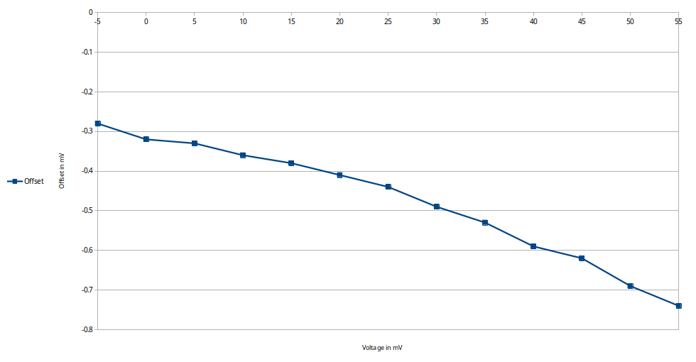
But currently, we have some problems with the accuracy of our measurements. For testing, we have connected a Beamex MC2 calibrator to analog input 0 and analog input 1 and are generating voltages between -5 and 55mV. But the measured voltages always have an offset of at least 1 - 1.5 percent. The offset also does not seem to be linear (see attached chart). We tried with different settings using different filters, different VBIAS value and chopping, but this produced similar results.

Also, sometimes the voltage jumped unexpectedly, up to 0.05 mV, like noise. This led to jumps in the temperature of around 1-1.2 degree celsius. We could not find a pattern in the noise.

All tests were done under room temperature.

For the test in the chart, we used the following settings:

1. Set the correct inputs in the Input Multiplexer register.

2. Disable the reference monitor and reference buffers, enable the internal reference in the Reference Control register.

3. Enable the PGA and set the PGA gain to 32 in the Gain Setting Register.

4. Set VBIAS to (AVSS + AVDD) / 2 and enable VBIAS on the correct input pin in the Sensor Biasing register.

5. Enable Chopping and sinc filter in the Datarate register.

This is the our schematic for the ADS124S08, we tried to keep it as close to the reference schematics in the datasheet as possible:
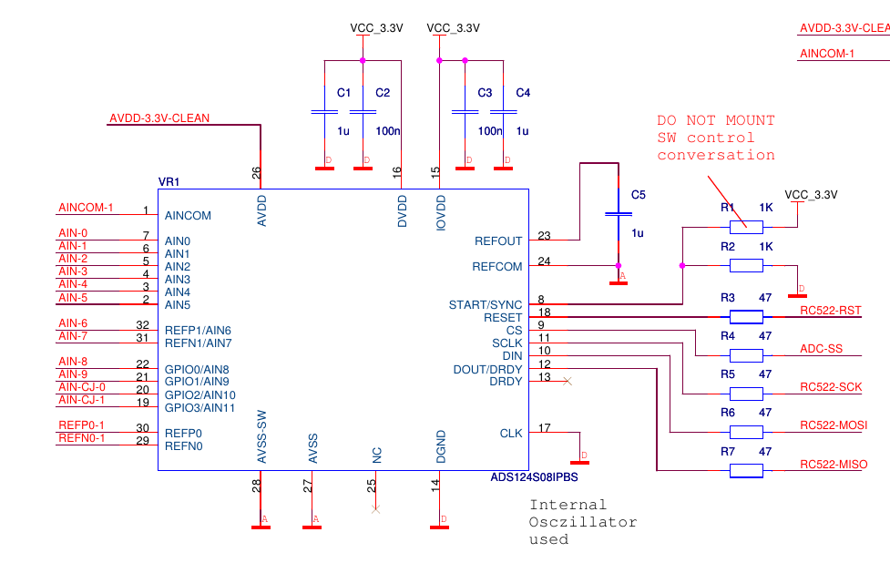
This is the schematic for the analog inputs:

So currently we are not sure if the error is caused by a wrong configuration of the converter, if we have an error in our schematic or if we just expect too high precision. Thanks in advance for any help!

Best regards,

Jakob

  • Hi Jakob,

    Welcome to the E2E forum!  I would suggest not using VBIAS for a couple of reasons.  Although the calibrator will output the correct voltage for the desired TC, it may present an issue if current is sinking or sourcing via VBIAS.  The calibrator will not have the same source impedance as the TC. 

    VBIAS is used to establish the correct input common-mode for the PGA.  However, there are also pull-up and pull-down resistors being used as well (R21, and R26) used for the same purpose.  The advantage of the pull-up and pull-down resistors is for checking for open wire detection.  For example, if the TC has a broken wire, the conversion result will be full-scale as one input is pulled to the supply and the other input to GND.

    When VBIAS is turned on, the current path will follow through the input series resistance and there will be a small current relative to the current divider created by the pull-up and pull-down resistor that will be reflected in a voltage drop across the series resistor. The actual voltage drop across R26 will be slightly different then at the AIN1 input where VBIAS would be established.  Turning off VBIAS should improve the linearity of the measurement and remove the offset.

    You may also find this Basic Guide to Thermocouple Measurements useful as well:

    http://www.ti.com/lit/an/sbaa274/sbaa274.pdf

    Best regards,

    Bob B

  • Hi Bob,

    thank you for you answer. We also tried with VBIAS turned off, but the offset and non-linearity remained.

    So I decided to do some tests with the ADS124S08 Evaluation board, so we did not use our board for this test. In the first test I configured it using the internal reference voltage source and used the following register settings:

    [ADS124S08 Register Settings]
    ID             	08
    STATUS         	00
    INPMUX         	04
    PGA            	00
    DATARATE       	14
    REF            	3A
    IDACMAG        	00
    IDACMUX        	FF
    VBIAS          	00
    SYS            	10
    OFCAL0         	00
    OFCAL1         	00
    OFCAL2         	00
    FSCAL0         	00
    FSCAL1         	00
    FSCAL2         	40
    GPIODAT        	00
    GPIOCON        	0

    I left all jumpers in the default positions and tried to read some data with the ADC Evaluation Tool. I used AIN4 and AIN0 and generated 1000mv, 900mv, ... up to 100mV.

    The voltages generated were correct, I verified this with a multimeter. But the voltages read by the ADC above 300mV had a large offset (see the image below, each step in the graph is a 100 mV step in the generated voltage where 1000mV is the first step).

    Then I tried measuring 50mV with PGA enabled and Gain = 32, but this led to results near zero, also in the Volts (Input Referred) chart.  (see image below)

    In the second test, I connected JP-8 to Vref and JP14 to use U27 and not the internal reference. JP11 was selected to connect REFN0 with AGND. Then I selected REFP0 and REFN0 instead of the internal reference and deactivated it, but the same results occured.

    Is there anything we might have overlooked like setting a jumper on the eval board or using a special setting for the ADC? Thank you in advance!

    Best regards,


    Jakob

  • Hi Jakob,

    It becomes a bit tricky when connecting an external supply voltage to the ADC inputs as there can be some potential difference between the external supply ground and the ADC ground.  I've have seen this to be as much as 40V for AC powered supplies. This means that if you connect an external supply to the ADC inputs you must make sure that you verify that the voltage is within the input range relative to AGND of the ADC.

    Specifically to your measurement when using the EVM, there are a couple of sections in the user's guide for the ADS124S08EVM that describe how you would connect a thermocouple at either J7 or J8.  In the GUI, there are user defined scripts that are configured for the various input connections.  Unfortunately you are not using one of them and your measurement is referenced to AGND through R70.  Most likely this is the source of the linearity and offset issues being seen with the EVM.

    I would suggest using the calibrator as the input source (as it is DC battery supplied), and connect the voltage the same way as described in the user's guide for TC input.  I would also install the pull-up and pull-down resistors (1 to 10M) to center the input voltage around 1/2 of the AVDD supply voltage.

    Best regards,

    Bob B