This thread has been locked.

If you have a related question, please click the "Ask a related question" button in the top right corner. The newly created question will be automatically linked to this question.

ADC12DJ2700: Initialisation error

Part Number: ADC12DJ2700

Hi to all,

we use the ADC12DJ2700 on one of our own boards.

In some cases we have a special error with the ADC:

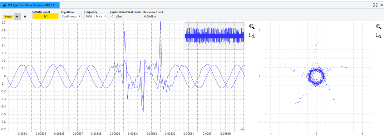
The noise floor in the spectrum is very high and seems to have a periodical ripple signal on it.

In the time domain we get a very ugly disturbed signal (testet with a sine signal an both ADC channels).

With the same setting and a new initialisation of the ADC we reach also an error free state:

Months ago I saw this behavior On the ADC12DJ2700 evalboard, too. But I assumed that this comes frome the early chip version. And after reinitialisation the error was gone. 

Do you have any experience with this bahavior?

Is there any problem with the JESD interface? Which steps do you suggest to improve the JESD connection?

Very interesting: sometimes in the error case the OVL-output pins from the ADC shows an overload.

We configure the ADC in JMODE9 MODE.

It would be very great if can give some hints.

Thanks a lot.

Best regards,

Paul Rott

  • Hi Paul,

    Can you please provide the register writes you perform to program the ADC? Also can you try running the ADC at lower sampling frequency and can you also try the ramp test mode see if you observe any error?

    Regards,

    Neeraj  

  • Hi Paul,

    If the ADC is left completely alone and just reset the FPGA side of the JESD204B link, does the error condition continue or does it get fixed?

    If this only resolves the problem by re-initializing the ADC what steps (clock startup, ADC register writes) are they using in the initial startup and what steps (register writes, any changes to clocking, etc.) in the re-initialization?

    Please confirm that the over-range signal that is being monitored is on the ORA0, ORA1, ORB0, ORB1 pins and not the OVR_Tx signals in the serial data stream.

    If seeing the ORxy pins toggling, then we would expect there is a problem with the initial ADC startup sequence that is resulting in unstable behavior.

    Regards,

    Rob

  • Hi Neeraj,

    thanks a lot for your response.

    I attached our .cpp-code for ADC-initialization. In the comments you can see, how the register writing is realized. The function "Write_ADC_SPI()" writes the register to the ADC.

    The last two digits from the hex-code are not used for programming the ADC.

    Running the ADC at lower sampling frequency is unfortunately not possible in our system.

    It's possible to run the ramp test, but therefore is no possiblity to detect the error case.

    At the moment the error case is detected by our device software, during measuring a sine signal.

    Best regards,

    Paul

    configure_adc.cpp

  • Hi Rob,

    thanks a lot for your response.

    It's a good input to reinitialize in error case the ADC or the FPGA and not both of them or the whole device.

    I attached the initialization sequence of the ADC at my reply to Neeraj. The sequence is used at the initial startup and at the reinitialization.

    The overrange information we recorded, were seen at the ORxy pins from the ADC.

    At the initialization sequence I am not sure about following parameters:

    - ADC: serializer pre-emphasis at register 0x48

    - FPGA: RX buffer delay at the JESD (at the moment we use there the value 0).

    Can you please give some advice?

    Best regards,

    Paul

  • Hi Paul,

    Are you still seeing the same issue?

    Regards,

    Neeraj

  • Hi Neeraj,

    yes, we still see the same issue...

    Debugging the FPGA brings following error message: ‘Unexpected K-character(s) received’ (output from FPGA Link Error Status Register).

    Do you have seen such errors (see screenshots above) at the evalboard, too?

    Best regards,

    Paul

  • Hi Paul,

    In your code can you please change the register write.

    Write the register Address 0x02A with the value of 0x22. DEVCLK_LVPECL should be set to 0.

    Regards,

    Neeraj

  • Hi Neeraj,

    thanks a lot for your input.

    I assume you mean, that we should write at register 0x02A the content 0x02?

    Bit 3...7 at register 0x02A are reserved bits (as shown in the datasheet).

    Best regards,

    Paul

  • Hi Neeraj,

    I was wrong, in the reserved register bits, bit 5 is set in default setting to one. So it results, that we have to write 0x22 into the register address 0x02A.

    I started a long time test, so see, if the error is gone.

    The datasheet says: "Use TAD_RAMP to reduce the probability of the JESD204B link losing synchronization; see the Aperture Delay Ramp Control (TAD_RAMP) section." (Datasheet SLVSEI0 –JANUARY 2018, SN1704017; page 42).

    Does this really mean, we can set the TAD_RAMP to eliminate the JESD link errors?

    By the way at the moment we switched to subclass 0 and still see the JESD link errors.

    Best regards,

    Paul

  • Hi Paul,

    Ok let see if the long time test give you positive results. 

    TAD  adjust is used to help with aligning the samples coming out of multiple devices and TAD_RAMP allow the user to slow the transition from one TAD setting to next TAD setting. In your system are you using TAD adjust feature?

    Regards,

    Neeraj 

  • Hi Neeraj,

    at the moment we are not using the TAD adjust feature.

    We only have one ADC device. But we use it in dual channel mode (JMODE9).

    So is guess that the TAD adjust feature won't bring success?

    At the moment the long time test runs without errors.

    We changed the DEVCLK_LVPECL_EN to "0" and did some improvements in the initialisation sequence of the whole system.

    Best regards,

    Paul