This thread has been locked.

If you have a related question, please click the "Ask a related question" button in the top right corner. The newly created question will be automatically linked to this question.

ADS114S08: Starting series resistor and shunt cap values - ADS114S08 single ended measurement

Part Number: ADS114S08
Other Parts Discussed in Thread: ADS1148

Greetings-

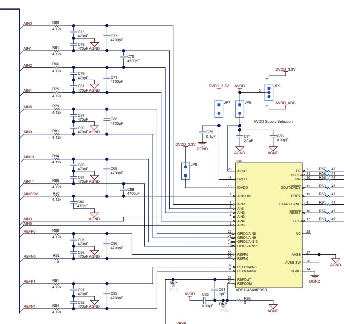
Using the ADS114S08 in a single ended measurement mode with PGA disabled and external 5V reference.

The two evaluation modules have vastly different passive components on the incoming AIN lines. Details are:

-differential coupling capacitor not installed

-using AIN0-7 with AINCOM referenced to AVSS

-5V external Vref

-PGA disabled

The older ADS1148 evaluation has analog in filters with vastly different values than what I assume is the more updated ADS1x4S08 evaluation module. I currently am utilizing a board layout with the 47ohm/47pF passive components and am considering moving this design to match the 4.12kohm/470pF component selection.

  • Hi Nick,

    Welcome to the E2E forum! The ADS1148 and ADS114S08 have totally different considerations with respect to input filtering on the EVM.  For the ADS1148, the input resistors were made small to lower the impact of error if the IDACs were routed through those inputs.  For the ADS114S08, the EVM was less a generic EVM and more specifically showing possible input configurations for various sensor types.  The input resistor was increased to limit current for a possible over-voltage condition.

    There are also some differences between the ADS114S08 and the ADS1148.  The you cannot take single-ended measurements with a  unipolar analog supply with the ADS1148, and you cannot use 5V for the reference voltage.

    As to specifics for the input filtering, you want to consider that the primary purpose of the filter resistor is to be used as a part of a low-pass antialiasing filter.  Secondary is as the purpose of limiting current to the input so that it does not exceed 10 mA in any condition where an over-voltage situation may occur.  You do not necessarily need to use the values shown in the EVM schematic

    Best regards,

    Bob B

  • Hi Nick,

    These are simply RC filters and quite often change based on what type of signal is being measured & the noise that is present in the environment.

    The previous design of 47ohm & 47pF has a cutoff frequency of approximately 72MHz, which is quite high. 

    The new design of 4.12k and 470pF has a cutoff frequency of approximately 82kHz. 

    There are a few general rules for sizing RC filters. You want the cutoff frequency to be at least one decade (10x) the maximum frequency of the signal of interest. This is to ensure that your signal of interest is not attenuated by the RC filter. You also want the RC filter to be significantly less (at least 2x) than the modulator frequency, which in this case is 256kHz. 

    I would recommend adopting the new RC filter design of 4.12k and 470pF.