Other Parts Discussed in Thread: ADS124S08
This is my major design and i want to measure the resistance sensor variable with a constant-current source.
fig1 show my hardware design
fig2 show my idea
i set the MUXCAL bit of the MUX1 register and insured device was working in Analog supply monitor. The Conversion result was right.
But i set the device with my idea and the conversion result was no right.
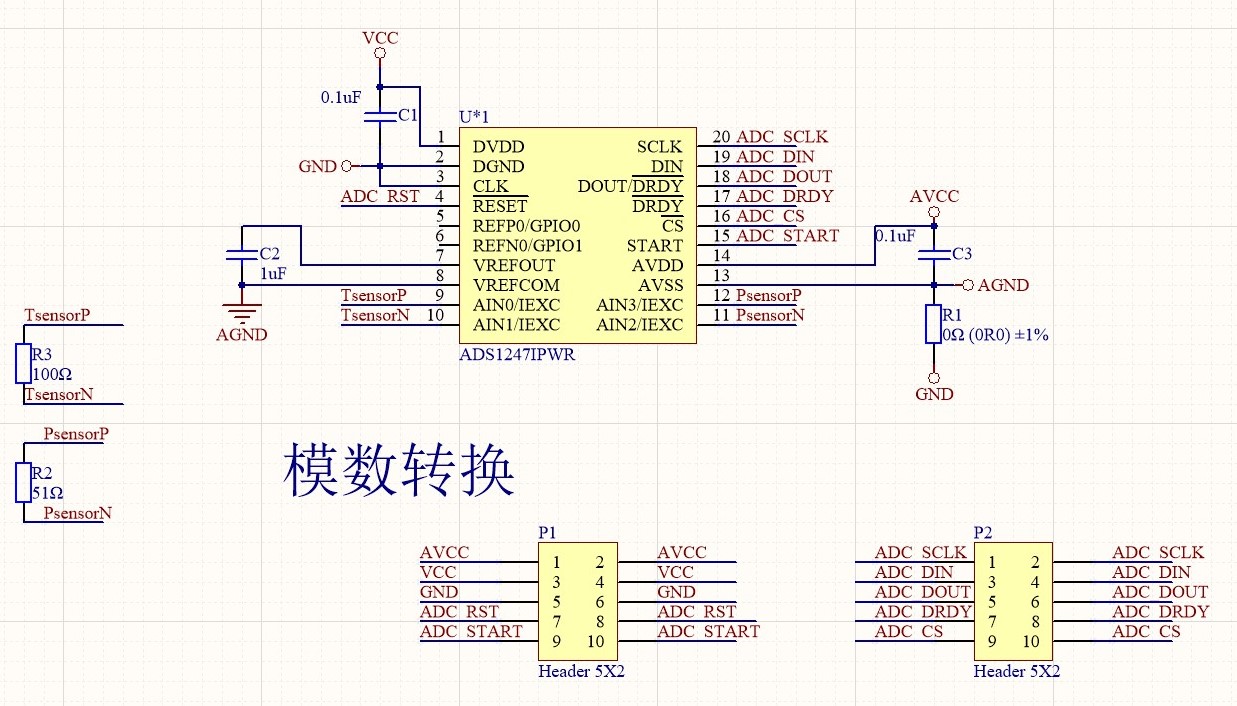
fig1 schdoc
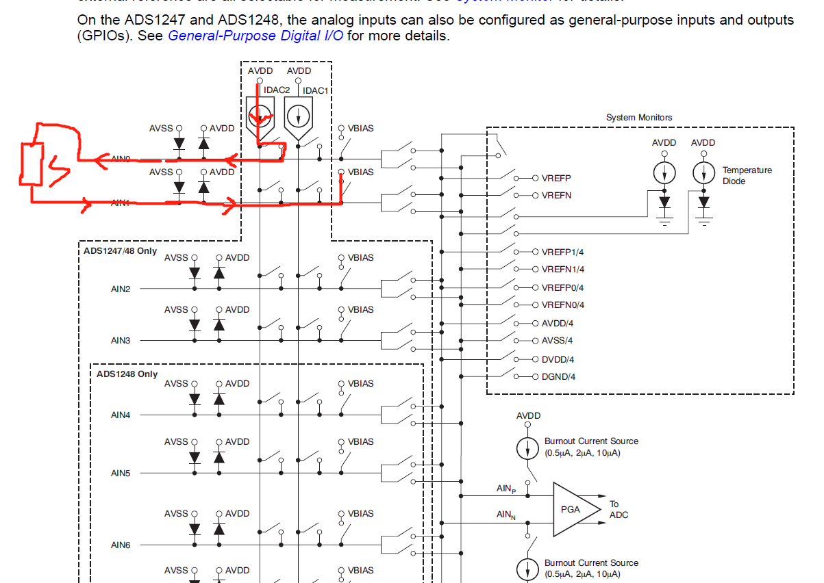
fig2 myidea
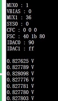
Debug1
![]()
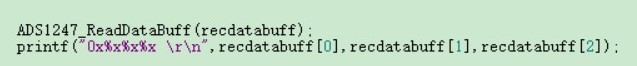
output format
![]()
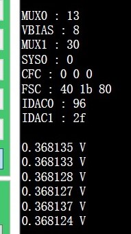
debug1 result

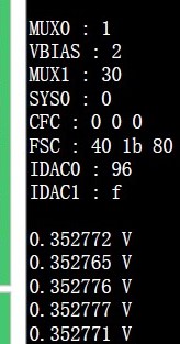
Debug2

debug2 result

Debug3

debug3 result