This thread has been locked.

If you have a related question, please click the "Ask a related question" button in the top right corner. The newly created question will be automatically linked to this question.

DAC80508: Output Broadcasting Issue

Anonymous
Anonymous
Guru 17045 points
Part Number: DAC80508

Hi 

My team is trying to output two distinct voltages from the device, and currently we are using the broadcast mode to output voltage#1 from OUT0, OUT2, OUT4, OUT6, and voltage#2 from OUT1, OUT3, OUT5, OUT7.

The exact steps are the following:

  1. Write 0x0400FF to SDI to set DIV to ÷1 and GAIN to ×2 in the GAIN register for initialization.
  2. Write 0x0255FF to SDI to set OUT0, OUT2, OUT4, OUT6 to broadcast mode in the SYNC register.
  3. Write 0x06 + (16 bits for voltage#1) in the BRDCAST register to broadcast voltage#1.
  4. Write 0x02AAFF to SDI to set OUT1, OUT3, OUT5, OUT7 to broadcast mode in the SYNC register.
  5. Write 0x06 + (16 bits for voltage#2) in the BRDCAST register to broadcast voltage#1.

However, the outputs are always 2.5 V, which seems to the REF voltage.

We also tried to output a voltage from OUT0 only as follows:

  1. Write 0x0400FF to SDI to set DIV to ÷1 and GAIN to ×2 in the GAIN register for initialization.
  2. Write 0x020000 to SDI for non-broadcasting mode and asynchronous mode in the SYNC register.
  3. Write 0x08 + (16 bits for voltage) to set voltage at OUT0 in the DAC0 register.

However, the output is still 2.5 V.

The only "responsive" thing is that when we set DIV to ÷2 (set that bit to HIGH), the voltage at the outputs becomes 1.25 V instead of 2.5 V.

For now we would like to know if the commands / values we are sending into SDI are correct for the requirement.

Thank you very much.

  • Hi, 

    Can you confirm if you are using the DAC80508M or the DAC80508Z variant?

    What are your supply voltages? Can you share your schematic?

    Thanks,

    Paul

  • Hi,

    Your configuration seems to be fine. As Paul mentioned, Can you confirm which variant are you using?

    Also are you giving enough time (min 10ns) after SCLK fall edge to CS rising edge?

    Please share your scope shots of  one write frame to have look at your timing, especially CS and SCLK, also DACx0508 requires data with the MSB as the first bit received.

    Regards,

    AK

  • Anonymous
    0 Anonymous in reply to Akhilesh K

    Hi 

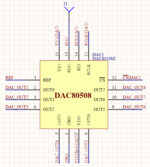
    The BOM part number we have been using is DAC80508MCRTET, and the schematic is as follow:

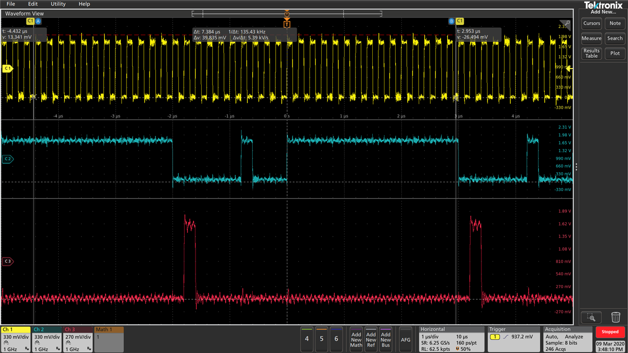
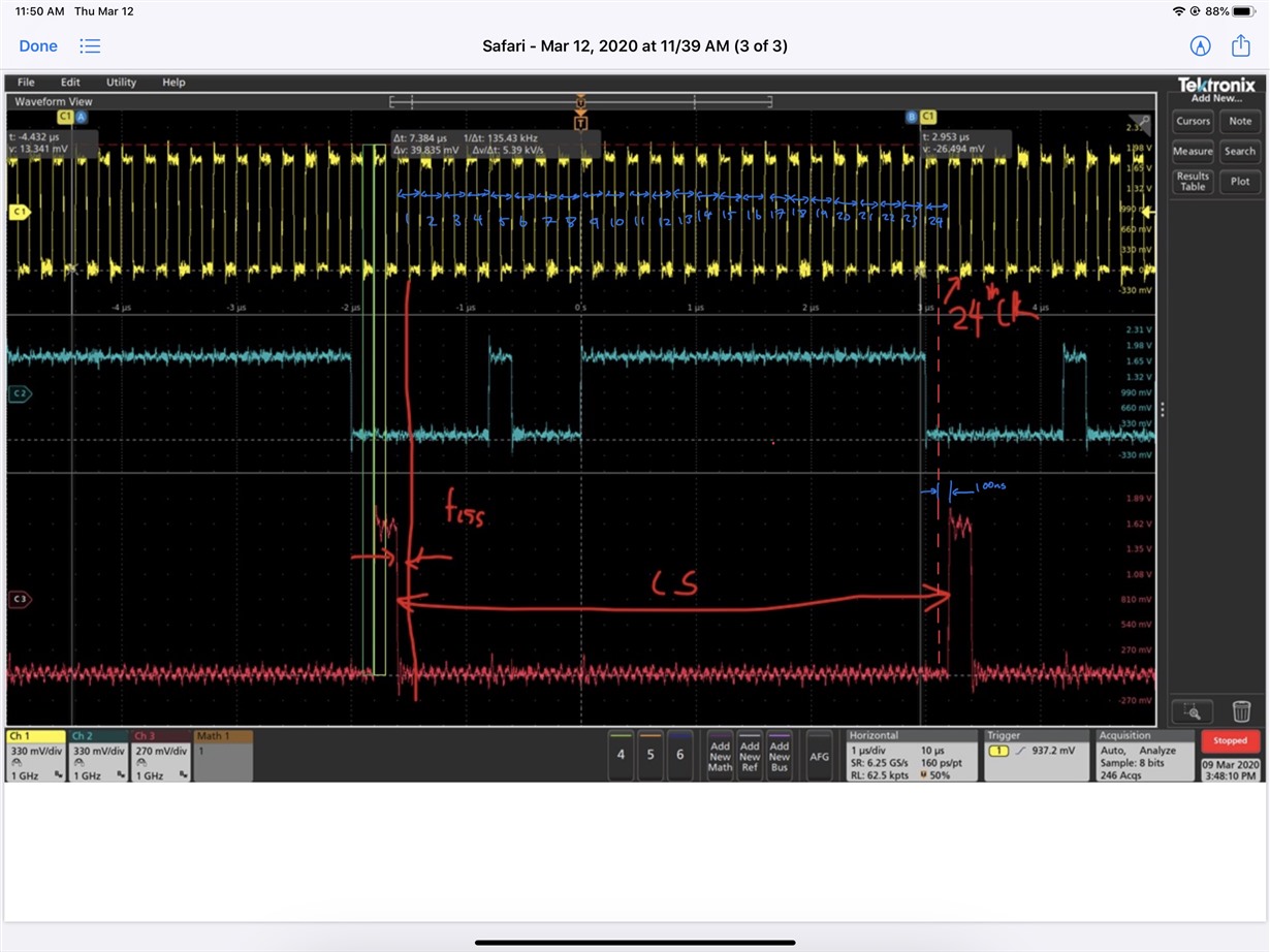
    The scope shot (yellow - SCLK, blue - SDI, red - CS) for outputting a voltage from OUT0 only:

    We sent MSB to the SDI pin first (0 at 23rd bit for "Write" command).

    Thank you very much.

  • Hi,

    From the scope shot it seems like CS goes high along with 24th falling edge of SCLK with no delay in between them (I may be wrong here, please verify)

    We need min 10ns between SCLK falling edge to CS rising edge. Can you please check this and add this delay? Similarly there is CS to SCLK falling edge setup (min 13ns).

    Regards,

    AK

  • Anonymous
    0 Anonymous in reply to Akhilesh K

    Hi Akhilesh

    Thank you very much for the reply.

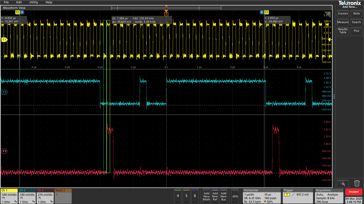
    From the figure, the gap (dark green rectangle) between the falling edge of SCLK and raising edge of CS is larger than 10 ns (around 100 ns). (One big grid is 1 us, and one small grid is 200 ns.) Similarly, the gap (light green rectangle) between CS rising edge and the next SCLK falling edge is around 100 ns as well.

    Perhaps my team is missing some time constraints or forget to send some necessary commands , but currently we cannot find anything.

    Thank you very much. 

  • Hi,

    Your one frame starts from CS going low to CS going high. There is CS to SCLK falling edge set up time of 13ns in your case its greater than 13ns as mentioned in the below pic.

    But then if I start counting SCLK, I am not seeing any delay between 24th SCLK fall edge to CS rising edge. Can you please clarify the same. May be I am missing since the scope shots are not zoomed in.

  • Anonymous
    0 Anonymous in reply to Akhilesh K

    Hi Akhilesh

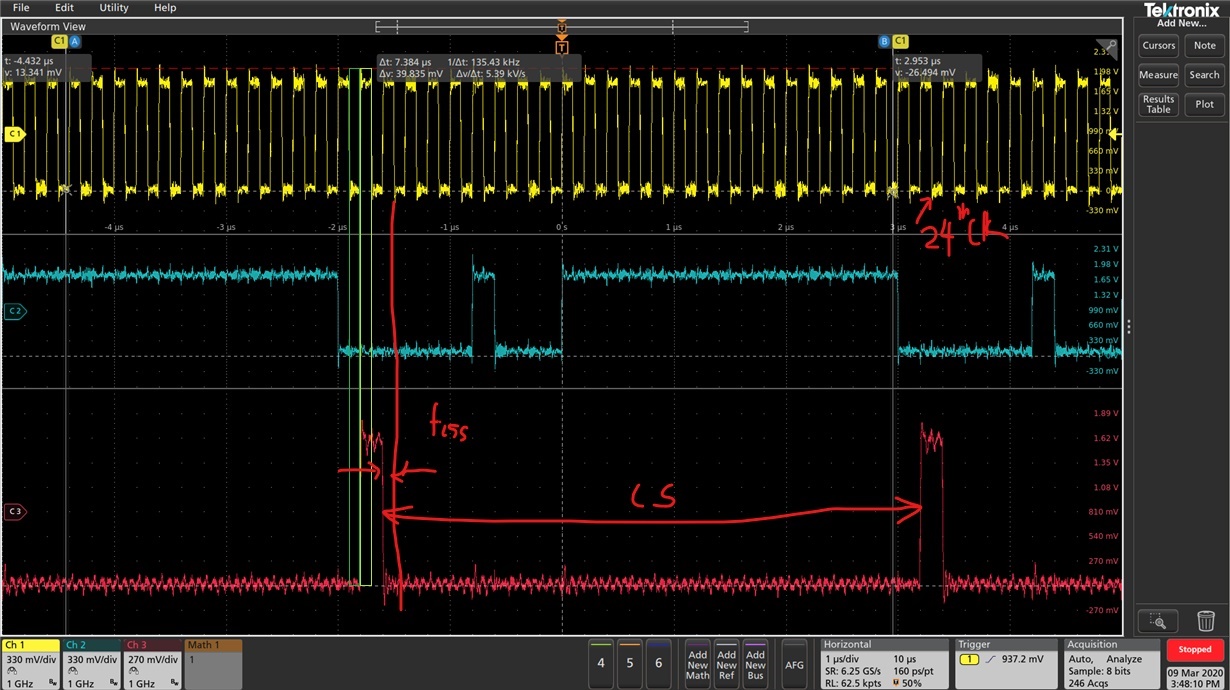
    Below is an annotated (blue marker) version of the SCLK count. The time between 24th falling edge and CS rising is 100ns (1/10th of time division from scope).

    All our signals are synchronous to SCLK posedge, while the DAC timing is relative to the falling edge. The clock period is 200 ns which means all the DAC timings we are considering are on the order of 100ns. 

    Thanks,

  • Hi,

    Since you are using M device ,and output range by default is 0 to 5V, you will get 2.5V as output by default on power up.

    After writing into corresponding DAC register (asynchronous mode), you should be able to see change in output voltage. Now I am really concerned why you are not able to get the device working. I have tried the following steps in our EVM

    1. Power up the device.

    2. Check the output, it reads 2.5V (Output to midscale for M device)

    2. Leave Gain register settings as is by default (DIV by 1 and Gain = 2)

    3. Write data into DAC1 register (I am using SPI mode 1), Just one frame. You dont need to write continuously

    4. Was able to see corresponding DAC output voltage .

    Can you please check these steps? SPI mode as well? please monitor your supply voltage as well when you are writing into device for any drop in voltage.

    Regards,

    AK