This thread has been locked.

If you have a related question, please click the "Ask a related question" button in the top right corner. The newly created question will be automatically linked to this question.

DAC108S085: Chcek the waveform

Part Number: DAC108S085

Hi team,

My customer plan to use DAC108S085.

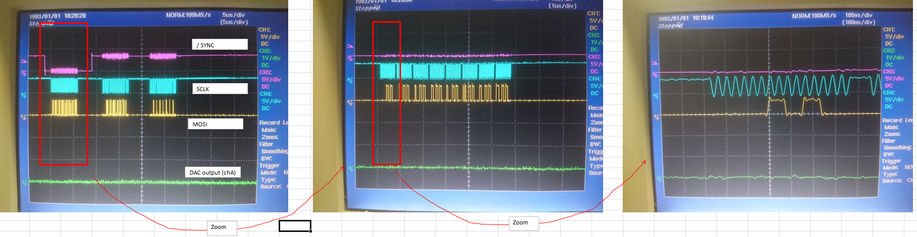
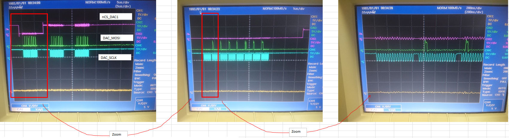
The customer would like to output the updated register on all channels at same time. After that the customer will change the /CS to 1.

Could you tell me whether this use case is correct or not? I've attached the waveform that the customer took.

Regards,

Yoshi

  • Hi Yoshi,

    This use case is not valid as there is a timing violation of SYNC (/CS) tSH (SYNC hold time after the 16th falling edge of SCLK) min is 3ns and max is (1/Fclk - 3) ns.

    One way to update all DAC simultaneously is using WRM mode. In WRM mode the registers of individual DAC can be written without updating output values.

    After writing into all registers change the device mode into WTM to update all DAC's output simultaneously.

    For more details about entering into WRM and WTM mode please see datasheet page no :17.

    Revert back to me if you need more clarifications.

    Regards,

    AK

  • Hi AK,

    Thanks for your answer.

    The customer can't see the 0.5V (0001100110) in their test when DAC output simltaneously.

    Test condition is as below.

    - SCLK : 25MHz

    - /SYNC : Change to 1 after DAC output simultaneously 8ch

    The waveform is below.

    Could you give your advice why the output is not correct?

    Regards,

    Yoshi

  • Hi Yoshi,

    As I mentioned earlier, this device has two modes of operation, one is WRM and WTM. By default on power up, its in WRM mode which means after writing into registers, you need to change mode to WTM by setting DB[15:12] to"1001". If you want change the values immediately after write, do the following steps.

    1. Power up the device

    2. Change device mode to WTM by setting DB[15:12] to"1001"

    3. Start writing into register by bringing SYNC low and making at high after 16clk cycles.

    4. Corresponding output will be reflected immediately.

    Check this for one channel as a debug.

    For simultaneous update of all channels please read through the description given in datasheet page number 19.

    Regards,

    AK

  • Hi AK,

    Thanks for your advice. The customer can see the output correctly.

    We have additional question from the customer.

    When the customer doing FTB test (Apply noise), they see the output voltage is not correctly. I've attached spread sheet which has waveform.

    I guess the output voltage maintain previous value because the device work correctly after retry to apply Vcc. (Turn off then turn on)

    1. Is there any way to reset the device via SPI? If yes, could you tell me how to set?

    2. Could you tell me how to recover from power-down mode via SPI?

    3. Usually this phenomenon as latch up, is there any way to solve by changing schematic? For example, adding diode on SPI line.

    Regards,

    Yoshi20200319 DAC108S085.xls

  • Hi Yoshi,

    Glad that customer problem got solved.

    Coming to resetting device through SPI mode, I am not able to find any info on datasheet or our internal docs. I will check with my design team, if they can provide any info on this.

    To recover device from power down mode through SPI, you can write into appropriate control register mentioned in datasheet table 3 and 4.

    I didn't understand your third point, could you please elaborate the same?

    Regards,

    AK

  • Hi AK,

    Could you tell me the timing chart regarding 1 and 2?

    Regards,

    Yoshi

  • Hi AK,

    Please ignore my previous post.

    Regarding 1, please let me know if there is any update.

    Regarding 2, To recover from power down mode, the customer should change write sequence as table 3. Am I correct?

     Regards,

    Yoshi

  • Hi Takahashi,

    You cannot reset this device through SPI, you can power down the device through SPI.

    yes, you need to use instructions from table 3 for recovering from power down mode.

    Regards,

    AK

  • Hi AK,

    Thanks for your answer.

    I'd like to confirm few more question. Could you support?

    When the customer implemented on their board, the customer seen the output of DAC108S085 suddenly keep holding the output voltage even though changing input after running few hours.

    The device seems to behave as power down mode.

    Then the customer added a command to recover from power down mode as A0FFh every 8ms. Then the device is working correctly.

    In summarize, the customer setting procedure is as below.

    1. Power up the device

    2. Change the device mode to WTM

    3. Start writing into register

    4. Restart the device by A0FFh every 8ms

    5. Start writing into register

    Is there any issue of this procedure?

    Please let me know if there is any solution to avoid keep holing the output voltage.

    Regards,

    Yoshi

  • Hi,

    Why are you restarting device (recover from power down mode) every 8ms ?  when you are writing data into device, are you instructing the device to go into power down as well?

    If no, you dont need step 4.

    Let me know whats the data customer is writing into device in each and every step, so that I can debug this further.

    Please note that device will not enter in power down mode its own unless instructed to do so :)

    Regards,

    AK

  • Hi AK,

    I understand step 4 is not needed. As I already mentioned the output voltage not change after run the device for few hours.

    After they add this action the device behave correctly again. That's why they are restarting device.

    1. Is this command not recommend to add?

    2. Do you have any idea why the device keep output voltage?

    Regards,

    Yoshi

  • Hi Yoshi,

    There is no problem in adding this command, I was wondering why its needed in first place?

    I have one question for you.

    1. After the power up, let customer write register through WTM mode and I believe they can see the change in output voltage immediately, right?

    Then after some time , if they write again with new data, they are not able to see the change in output voltage? If this is the case are they writing the register with bit 15 as '0' or '1'  ?

    Regards,

    AK