This thread has been locked.

If you have a related question, please click the "Ask a related question" button in the top right corner. The newly created question will be automatically linked to this question.

ADS1018-Q1: Leakage Current on analog input pins

Part Number: ADS1018-Q1

Hi Team,

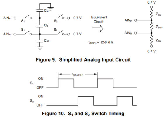
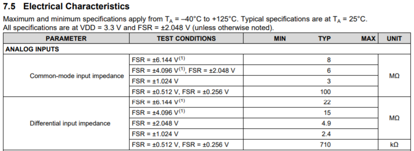
Our customer would like to know the leakage current on the 4 Analog Input pins of ADS1018QDGSRQ1 if they will connect it to any voltage divider network. What will be the leakage current that will be passing to ground through the analog pins in VSSOP package? 

Please let me know if you need more information from the customer.

Thanks!

Jonathan

  • Jonathan,


    Is your customer worried about the loading of the resistor divider by the ADC input? If this is the case, the input currents going into the ADC appear more like a resistive load on the divider. The input for ADS1018-Q1 uses a switched cap for sampling the input voltage. Because of this, the input appears as an input impedance with differential and common-mode components. From the inputs, it appears like this as a schematic:

    These impedances depend on the FSR range. They are listed in the Electrical Characteristics table here:

    If the input is connected to a resistive voltage divider, then the input currents from these equivalent resistances will cause some error. For this reason, you would probably want to use resistors lower than 100k depending on the FSR. With the diagram in the datasheet and the values in the Electrical Characteristics table, your customer should be able to calculate the error based on these numbers.


    Joseph Wu

  • Hi Joseph,

    Thank you for your support on this thread.

    Let me share this to our customer and will let this thread put to "resolved" if this is okay with him.

    Regards,

    Jonathan