This thread has been locked.

If you have a related question, please click the "Ask a related question" button in the top right corner. The newly created question will be automatically linked to this question.

CCS/ADS1220: How can I get the conversion data?

Part Number: ADS1220

Tool/software: Code Composer Studio

Dear

I try to get the sensor data from ADS1220 by SPI Communication on DRV8301-HC-EVM.

I modified the SPI-A Port (J8) of the DRV8301-HC-EVM. First remove the chip U5 and connect the wire to the ADS1220 Module.

I sent the command to the ADS1220. It works and response. But, I can not read the conversion data. There is nothing on DOUT channel from Slave.

What is the problem?

Below the captured image.
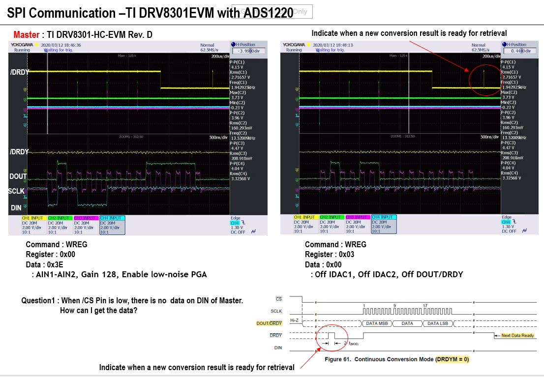
CCS Codes

=======================

void HAL_setupSpiA(HAL_Handle handle)
{
HAL_Obj *obj = (HAL_Obj *)handle;

SPI_reset(obj->spiAHandle); // Reset SPI

SPI_setClkPolarity(obj->spiAHandle,SPI_ClkPolarity_OutputRisingEdge_InputFallingEdge);
SPI_disableLoopBack(obj->spiAHandle);
SPI_setCharLength(obj->spiAHandle,SPI_CharLength_8_Bits);

SPI_setTriWire(obj->spiAHandle, SPI_TriWire_NormalFourWire);
// SPI_setTriWire(obj->spiAHandle, SPI_TriWire_ThreeWire);

SPI_setMode(obj->spiAHandle,SPI_Mode_Master);
SPI_setClkPhase(obj->spiAHandle,SPI_ClkPhase_Normal);
// SPI_setClkPhase(obj->spiAHandle,SPI_ClkPhase_Delayed);
SPI_enableTx(obj->spiAHandle);

SPI_enableChannels(obj->spiAHandle);
SPI_enableTxFifoEnh(obj->spiAHandle);
SPI_enableTxFifo(obj->spiAHandle);
SPI_setTxDelay(obj->spiAHandle,0);
SPI_clearTxFifoInt(obj->spiAHandle);
SPI_enableRxFifo(obj->spiAHandle);

// BaudRate setting is not needed for slave mode
// 4MHz for Turbo Mode 2KSPS, so SPIBRR = 21, 4MHz
SPI_setBaudRate(obj->spiAHandle,(SPI_BaudRate_e)(0x0015)); // 0001 0101 --> 101, 5MHz
SPI_setSuspend(obj->spiAHandle,SPI_TxSuspend_free);
SPI_enable(obj->spiAHandle); // Enable SPI

return;
} // end of HAL_setupSpiA() function

============================================================

if((bCfgRegs == false) && (bStartSync == false))
{
switch(addrCfgReg){
case 0:
{
// WR, CFG0, AIN1-AIN2, Gain 128, Enable low-noise PGA
spiTxCmdCFG(0x40); // 0100 0000
spiTxCmdCFG(0x3E); // 0011 1110

addrCfgReg++;
break;
}
case 1:
{
// WR, CFG1, 2KSPS, Turbo mode, Continuous mode, Off Temp Sensor, Off Current Source
spiTxCmdCFG(0x44); // 0100 0100
spiTxCmdCFG(0xD4); // 1101 0100, Turbo Mode
// spiTxCmdCFG(0xC4); // 1100 0100. Normal Mode

addrCfgReg++;
break;
}
case 2:
{
// WR, CFG2, Vref AIN0-AIN3, Off FIR, Off PSW, Off IDAC
spiTxCmdCFG(0x48); // 0100 1000
spiTxCmdCFG(0x80); // 1000 0000

addrCfgReg++;
break;
}
case 3:
{
// WR, CFG3, Off IDAC1, Off IDAC2, On DOUT/DRDY
spiTxCmdCFG(0x4C); // 0100 1100
// spiTxCmdCFG(0x02); // 0000 0010, On DOUT/DRDY
spiTxCmdCFG(0x00); // 0000 0000, Off DOUT/DRDY

addrCfgReg = 0;
bCfgRegs = true;
break;
}

==================================================

void spiTxCmdCFG(uint16_t data)
{
HAL_Obj *obj = (HAL_Obj *)halHandle;

// reset the Rx fifo pointer to zero
// SPI_resetRxFifo(obj->ads1220.spiHandle);
// SPI_enableRxFifo(obj->ads1220.spiHandle);

uint16_t spiCmdReg;

spiCmdReg = data; //Reset
SPI_write8(obj->ads1220.spiHandle, spiCmdReg);

// Clear SPI Interrupt flag
SPI_clearTxFifoInt(obj->ads1220.spiHandle);

return;}

  • Hi Jaehoon,

    When you see DRDY transition from high to low as you show in the figures, this means that the new conversion result data are ready to be retrieved from the ADS1220.  The key word here is 'retrieved'.  You must use some action on the SPI bus to retrieve the data.  The ADS1220 is not an SPI master, but rather a slave.  The ADS1220 cannot initiate SCLKs.  So just like when you read or write the configuration registers you must use a similar action by initiating the transfer by the micro.

    There are two different methods to retrieve the data.  One is by reading the data direct.  This is accomplished by setting CS low and by transmitting 3 dummy bytes (NOP) of data to initiate the SCLKs.  After the 3 bytes of data are received you then set CS high.

    The second method is to use the RDATA command.  Using this method you set CS low and issue (transmit) the RDATA command followed by transmitting 3 dummy bytes (NOP) to the ADS1220 and then after the data are received you set the CS high.

    Best regards,

    Bob B

  • Hi Bob.

    Thank you for your help.

    I tried the method of reading the data direct.

    First, check the /DRDY by external interrupt 1.

    Send, set CS low and by transmitting 3 dummy bytes (NOP) of data to initiate the SCLKs.  read the buffer when the RX interrupt occurred, After the 3 bytes of data are received , set CS high.

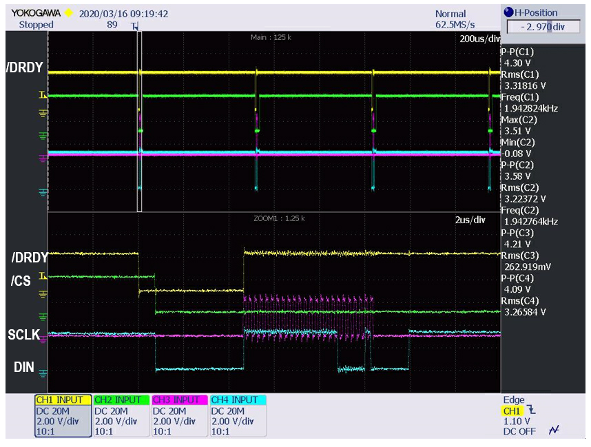
    Here is the codes and captured image.

    Interrupt Setup ---------------------------------

    //
    // Enable XINT1 and XINT2 in the PIE: Group 1 interrupt 4 & 5
    // Enable INT1 which is connected to WAKEINT
    //
    PIE_enable(obj->pieHandle); // Enable the PIE block
    PIE_enableInt(obj->pieHandle, PIE_GroupNumber_1, PIE_InterruptSource_XINT_1); // Enable PIE Group 1 INT4
    CPU_enableInt(obj->cpuHandle, CPU_IntNumber_1); // Enable CPU INT1

    // SPI TX,RX
    PIE_enableInt(obj->pieHandle, PIE_GroupNumber_6, PIE_InterruptSource_SPIARX); // Enable PIE Group 6, INT 1
    CPU_enableInt(obj->cpuHandle, CPU_IntNumber_6); // Enable CPU INT6
    EINT; // Enable Global Interrupts


    //
    // GPIO29 is XINT1
    //
    EALLOW;
    GPIO_setExtInt(obj->gpioHandle,GPIO_Number_29,CPU_ExtIntNumber_1); // XINT1 is GPIO29
    EDIS;

    //
    // Configure XINT1 and XINT2
    //
    PIE_setExtIntPolarity(obj->pieHandle, CPU_ExtIntNumber_1, PIE_ExtIntPolarity_FallingEdge);

    //
    // Enable XINT1 and XINT2
    //
    PIE_enableExtInt(obj->pieHandle, CPU_ExtIntNumber_1);

    //
    // GPIO19 will go low inside each interrupt.
    //
    EALLOW;
    // SPI-STE
    GPIO_setMode(obj->gpioHandle,GPIO_Number_19,GPIO_19_Mode_GeneralPurpose); //GPIO_19_Mode_SPISTEA_NOT
    GPIO_setDirection(obj->gpioHandle,GPIO_Number_19,GPIO_Direction_Output);
    GPIO_setPullup(obj->gpioHandle,GPIO_Number_19,GPIO_Pullup_Enable);
    EDIS;

    EINT; // Enable Global Interrupts

    SPI-A Setup ------------------------------------------------------------

    //! Reset SPI for changing configuration
    SPI_reset(obj->spiAHandle);

    //! SPI CCR (Configuration Control Register)
    SPI_setClkPolarity(obj->spiAHandle,SPI_ClkPolarity_OutputRisingEdge_InputFallingEdge);
    SPI_disableLoopBack(obj->spiAHandle);
    SPI_setCharLength(obj->spiAHandle,SPI_CharLength_8_Bits);

    //! SPI CTL (Operation Control Register)
    SPI_enableOverRunInt(obj->spiAHandle); // the OVERRUN INT ENA bits in the SPICTL register
    SPI_setClkPhase(obj->spiAHandle,SPI_ClkPhase_Normal); // the CLOCK PHASE bits in the SPICTL register
    SPI_setMode(obj->spiAHandle,SPI_Mode_Master); // he MASTER/SLAVE bits in the SPICTL register
    SPI_enableTx(obj->spiAHandle); // the TALK bits in the SPICTL register

    //! SPI ST (Status Register)
    obj->spiAHandle->SPIST = 0x0000;

    //! SPI BBR (Baud Rate Register)
    //! BaudRate setting is not needed for slave mode
    //! 4MHz for Turbo Mode 2KSPS, so SPIBRR = 21, 4MHz
    SPI_setBaudRate(obj->spiAHandle,(SPI_BaudRate_e)(0x0015)); // 0001 0101 --> 101, 5MHz

    //! SPI FFTX (Transmit Register): 1100 0000 0010 0010
    SPI_enableChannels(obj->spiAHandle); // Reset the SPI RX/TX channels
    SPI_enableTxFifoEnh(obj->spiAHandle); // FIFO enhancements enable
    SPI_clearTxFifoInt(obj->spiAHandle); // TX FIFO Interrupt Clear
    SPI_enableTxFifoInt(obj->spiAHandle); // TX FIFO Interrupt enable
    SPI_setTxFifoIntLevel(obj->spiAHandle, SPI_FifoLevel_1_Word); //set TX FIFO level to 2

    //! SPI FFRX (Receive Register) : 0x0022 (10 0010)
    SPI_enableRxFifoInt(obj->spiAHandle); // RX FIFO Interrupt enable
    SPI_setRxFifoIntLevel(obj->spiAHandle, SPI_FifoLevel_2_Words); //set RX FIFO level to 2

    //! SPI FFCT (FIFO Control Register)
    SPI_setTxDelay(obj->spiAHandle,0);

    //! SPI PRI (Priority Control Register)
    SPI_setSuspend(obj->spiAHandle,SPI_TxSuspend_free);

    //! Enable SPI
    SPI_enable(obj->spiAHandle); // Enable SPI

    //! TX FIFO Reset, RX FIFO Reset
    SPI_enableTxFifo(obj->spiAHandle); // Transmit FIFO reset
    SPI_enableRxFifo(obj->spiAHandle); // Receive FIFO reset

    ISR Routine -----------------------------------

    interrupt void spiRdyISR(void)
    {

        HAL_Obj  *obj = (HAL_Obj *)halHandle;

    GPIO_setLow(obj->gpioHandle, GPIO_Number_19); // SPI-STE

    // Wait for the ADS1220 registers to update
    delayLoop(1); //usec

    // initiate the SCLKs.
    spiTxDummyData();

    HAL_acqAdsRdyInt(halHandle); // Acknowledge interrupt from PIE group 1, CPU INT1

    }

    interrupt void spiRxFifoISR(void)
    {
    HAL_Obj *obj = (HAL_Obj *)halHandle;


    while(SPI_getRxFifoStatus(obj->ads1220Handle->spiHandle) != SPI_FifoLevel_Empty)
    {
    gSpiVars.RxData[gSpiVars.RxNum++] = SPI_read(obj->ads1220Handle->spiHandle);
    }

    GPIO_setHigh(obj->ads1220Handle->gpioHandle, GPIO_Number_19);

    // Clear Overflow flag
    SPI_clearRxFifoOvf(obj->ads1220Handle->spiHandle);

    // Clear Interrupt flag
    SPI_clearRxFifoInt(obj->ads1220Handle->spiHandle);

    // Acknowledge interrupt from PIE group 6, CPU INT6
    HAL_acqAdsSpiInt(halHandle);

    return;

    }