This thread has been locked.

If you have a related question, please click the "Ask a related question" button in the top right corner. The newly created question will be automatically linked to this question.

ADS1256: Best performance method for delta-sigma AD

Part Number: ADS1256

Hi,

I'm trying to use the differential mode of the ADS1256(www.seeedstudio.com/Raspberry-Pi-High-Precision-AD-DA-Board.html) to measure input voltages in the range 0-5V, for 3 inputs(ch0-1,2-3,4-5).And I want to know device performance, so I connect together AINp and AINn by short pin.

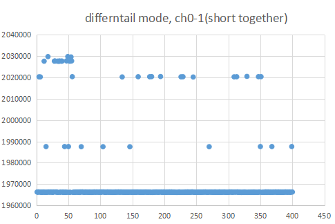
I measured data for 400 points(Differential ,Gain 1, Buffer off, auto calibration off, calibration before measure by SELFCAL). This result data is attached. So, my questions is below.

1)Why result data is not stable? Why data is like steps?
2)This data accuracy is not good, So I want to compare my data(differential input measurement in short pins) to another. Does anyone have this data?
3)How to measure devices performance in my device? I try short pins and measured it. is this correct?
4)Which measurement method is best for this device?(ex. diff, buffer on, PG=1...)

Any idea? Thanks.
--
YH

  • Hi Hara-san,

    Shorting the inputs of the ADS1256 together and taking a reading is a good way to measure the ADC's noise. This is actually what we do in many cases to characterize the ADC noise you see in the datasheet. You can compare the values you see in your test to the values in Tables 1-6 in the ADS1256 datasheet. You can match your settings to the specific table (Buffer on vs Buffer Off), as well as the data rate and gain setting you chose. So yes, you are performing the correct test to understand the noise of the ADC. I believe this answers Questions #2, #3 and #4 in your post.

    Applying a differential input to the ADC should result values near 0 code (000000h). So I am confused what you are showing in your plot where most of the codes are around a decimal value of 1965000, or 0.59 V if VREF = 2.5 V and G =1. Perhaps if you can provide a better description of the tests you are taking as well as the raw ADC values you see (in Hex), that would help.

    Are you performing a calibration as well? I think I understood your post to mean that you are performing a SELFCAL before you took the measurements shown in the plot in your post - is that correct? What are the values in your FSC and OFC registers after performing the SELFCAL?

    The link you provided did not work, but it seems like you might be using the Waveshare board that has the ADS1256 on it. Is that correct? Please note that we did not provide support for this board since it is not developed by TI, but we can offer help on the use of the ADS1256 device.

    Please provide the answers to my questions and I will work with you to try to find the cause of this issue.

    -Bryan

  • Hi Bryan,

    Thank you for your advice. 

    Bryan Lizon86 said:
    Shorting the inputs of the ADS1256 together and taking a reading is a good way to measure the ADC's noise.

    Yes, I always calibrating at before measuring. Calibration Register value is always chnageing, such as like this.

    ~

    STATUS:30 MUX:01 ADCON:20 DRATE:A1 IO E1 OFC0:30 OFC1:04 OFC2:00 FSC0:D2 FSC1:A6 FSC2:49

    ~

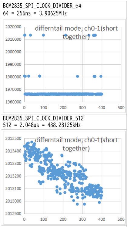
    And I found this iregular reason. That was SPI clock rate.
    If I decrese SPI clock rate, I could get correct data. Sometimes it didn't work, so I didn't know the cause.

    However, it seems that speed alone is not the cause, so I will review communication such as waiting time again.

    Thanks!! My problem is clear!

    --

    Yukihisa Hara

  • Hi Hara-san,

    Glad you have identified where the issue might be.

    Please note that the ADS1256 datasheet defines the minimum and maximum SCLK period - I have copied the relevant information below.

    I assume you are using a 7.68 MHz clock, but even if you were using the maximum allowable 10 MHz clock, then τCLKIN = 100 ns. As shown in the image below, the SCLK period must be 4x greater than the τCLKIN, or in this case 400 ns, which is a 2.5 MHz. SCLK frequency

    So, 2.5 MHz represents the maximum SCLK frequency you can use with a 10 MHz clock, though if you used a 7.68 MHz clock then SCLK (max) = 1.92 MHz.

    I am not sure if this is the only issue in your system, but it is certainly one of them.

    -Bryan

  • HI Bryan!

    Thank you for your reply, and I'm sorry for rate response.

    I will check maximum clock rate. I don't forgot this point.

    Everything is good by your advice now.


    Best regards,

    --

    Yukihisa Hara