Part Number: ADS1293EVM
Other Parts Discussed in Thread: ADS1293
I have been working on a project that aims to detect fetal heart rate during pregnancy. For this purpose, I have designed the setup listed below:
- 1x ADS1293EVM board and the provided software
- 1x 5 Lead ECG Cable with a DB9 connector
- 5 electrodes positioned in various places of the chest and body
The reason to use the ADS1293EVM has been the ease of setup and the software that comes with the board. I have also noticed that the TI also offers an ADS1293 front end module, which I do not have any idea as to what the difference is between the 2.
Using the EVM board, I have managed to perfectly detect the heart rate of the mother, but have had very little luck with the fetal heartrate. Typically, one should be able to see a much smaller peak, in between the larger peak of the mother’s heartbeat.
1 - Does anyone have any idea as to whether this is the right setup to use or I have chosen the wrong board for such a project?
I have had the idea of linking more than 1 board together, in a master and slave setup, in order to allow for higher number of leads to be used in order to cover more positions on body. However, there are no info on such a setup anywhere on the ADS1293EVM board data sheet or the web.
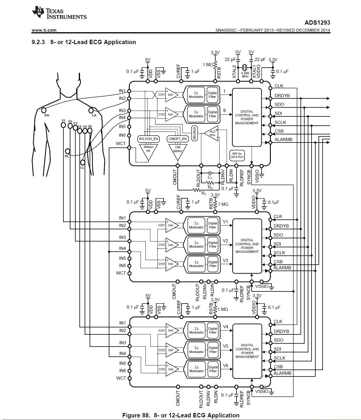
The only info I have found came from the data sheet of the ADS1293 front-end module as shown in the attached picture. It shows 3 of these chips connected together, allowing for 8 to 12 leads to be attached in various configurations. I have very little info on how to connect such boards together and the data sheet is extremely unclear and I would appreciate if you could clarify the point below.
2 – What is the difference between the ADS1293 and ADS1293EVM? They are 2 different parts listed on the TI website.
3 – Based on the attached picture from the ADS1293 data sheet, can the ADS1293EVM board also be linked up as master and slave in the same manner? Or the ADS1293EVM is treated as a complete board that is final and cannot be added to other similar equipment?
4 - If so, how one can link up the necessary point and connectors between the 3 boards? I have very little knowledge on this.
5 – The example shown in the picture is for 10 leads. If I want to use the setup for either 9 or 12 lead configurations, do I just simply link up any free IN pins for that purpose?
6 – Let assume that I have managed to link up the 3 boards together. On the attached picture, the leads seem to be individually linked to the 3 boards. How one can do such a thing if you are using a lead with either a DB9 connector for 9 leads or a DB12 connector for 12 leads?
I would really appreciate any help in clarifying these points or a referral to any page that may show examples. My knowledge on such setups is not advanced enough to move forward unfortunately.