This thread has been locked.

If you have a related question, please click the "Ask a related question" button in the top right corner. The newly created question will be automatically linked to this question.

ADS1292R: No ECG Output

Part Number: ADS1292R
Other Parts Discussed in Thread: ADS1292, , CC2650MODA

Hello,

I am working on the IC ADS1292 to get ECG output.

I am using Single Channel (Ch - 1), with no respiration circuitry.

I have done the SPI communication and verified it by setting different data rates and checking whether the data rates are being changed or not.

I have attached the DRDY signal to the Positive edge interrupt. (This happens only when i send a command to trigger it, otherwise, it is disabled)

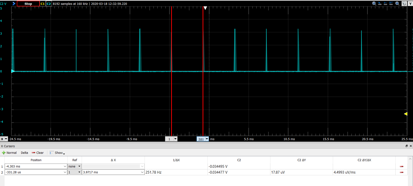
So I am able to see the DRDY as follows (before providing the trigger). Sampling Rate is set to 250Hz. (Hence concluding that SPI Communication working fine).

Now i send a trigger command to read the data, so DRDY is set to Positive edge interrupt. Now when i scope at DRDY signal.

I get something like this,
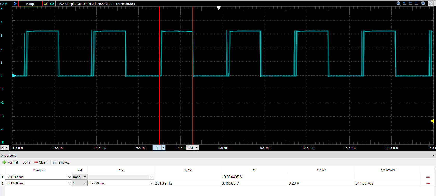
I don't know what is wrong Please help me out.

At RXBUF when i am reading Channel 1 data, I am getting => 7F FF FF (Hex).

Regards,

Mohin

  • Sorry for the  mistake, The first image is supposed to be like this.

  • Hello Moin,

    Thank you for your post.

    /DRDY is an active-low interrupt that indicates new data is ready with each falling edge. The interrupt is cleared with the first SCLK falling edge, which can happen either when sending a command or reading data. If the /DRDY interrupt is never cleared, the ADS1292R will clear it automatically just a few master clock periods before the next interrupt arrives. Figure 38 in the data sheet illustrates how /DRDY idles low when data is not read. 

    If you are operating in RDATAC mode (default), you'll need to complete the data read operation in between /DRDY falling edges. Failure to do so will result in corrupt data. Please refer to pages 36 and 37 for more information on the RDATAC and RDATA modes.

    Best regards,

  • Hello Ryan,

    Thanks a lot, I figured it out. Read the DRDY at the negative edge. Seems like DRDY is fine now.

    But still, ain't getting past the saturation of  0x7F FF FF.

    Can you help me get through this too?

    Regards,

    Mohin

  • Also, there is this issue that i am not getting Vref = 2.42V at Vrefp.

  • Hello Moin,

    Those two issues are likely related. Without a reference voltage, the ADC has nothing to compare the input to. The internal reference buffer needs to be enabled in the register settings.

    I suggest revisiting the Initial Flow at Startup diagram in the data sheet. We also have some basic startup debug tips in our ADS129x E2E FAQ page.

    Best regards,

  • Hello Ryan,

    Thanks for the reply. 

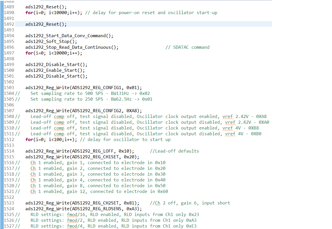
    Can you please take a look at my initialization?

    I have provided it below. Please check to see if i am missing anything.

  • As for the Vref, I have already enabled the buffer, but sometimes i get Vref = 2.42V and sometimes i am getting -30mV.

    I have been trying to debug this issue but haven't reached a conclusion.

    So please check my initialization and tell me if I am making any mistake anywhere.

    Regards,

    Mohin

  • Hello Mohin,

    At the beginning of the routine, you are trying to write to the CONFIG2 register before sending the SDATAC command. Please send the SDATAC command before any other commands, as explained in the start up diagram in Figure 63. Also, after RESET, the device will default to RDATAC mode. The order of operations must be RESET -> SDATAC -> WREG... The state of the START pin does not affect the ability to read/write registers.

    Best regards,

  • Thanks for replying back.

    So i followed your steps and the following.

    I did the following but still, i am having the same issue.

    When i upload the program, Vref = 2.42V.

    When i disconnect the USB and connect the USB for power again, the Vref = -60mV.

    Now i am stressing coz this is unexpected behavior.

    I got a roundabout way, where i initialize the ADS1292 every time i want to read the data.

    So it's like whenever i want to read the data i initialize the ADS1292.

    But still getting no ECG data.

    getting the following.

    Please help me.

    Regards

    Mohin

  • Hi Mohin,

    When you disconnect power, the ADS1292R will not retain it's register settings. You only need to initialize the device one time after power-up, unless a /RESET or /PWDN is issued.

    The data capture you shared shows nothing that is helpful for debug purposes. There is no information about the applied input signal, how the signal is connected to your circuit, what your circuit looks like, etc. I strongly suggest that you take a step back and take the time to understand the signal chain. The ADS1292R includes an internal square wave test signal, which you can use to validate your ability to read data correctly before applying an external signal. My next suggestion would be to apply a known signal from a function generator (i.e. a sine wave) and validate the connection from the signal source through the entire signal chain. Trying to measure a live ECG directly allows for too many unknown variables.

    Regards,

  • Hello Ryan,

    I'm sorry for providing so little and irrelevant information.

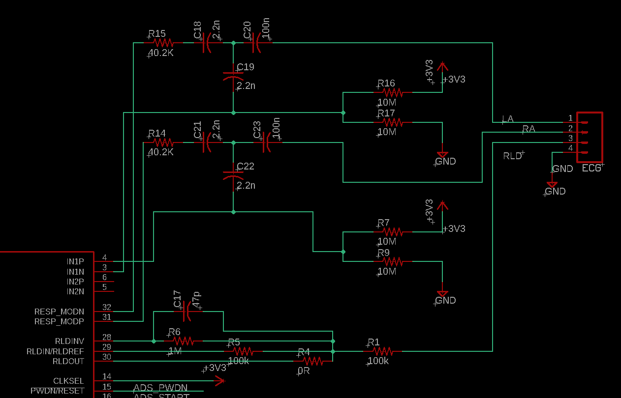
    The circuit for the input is shown below.

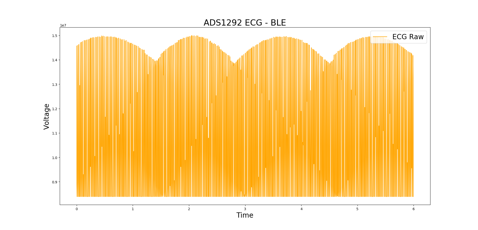
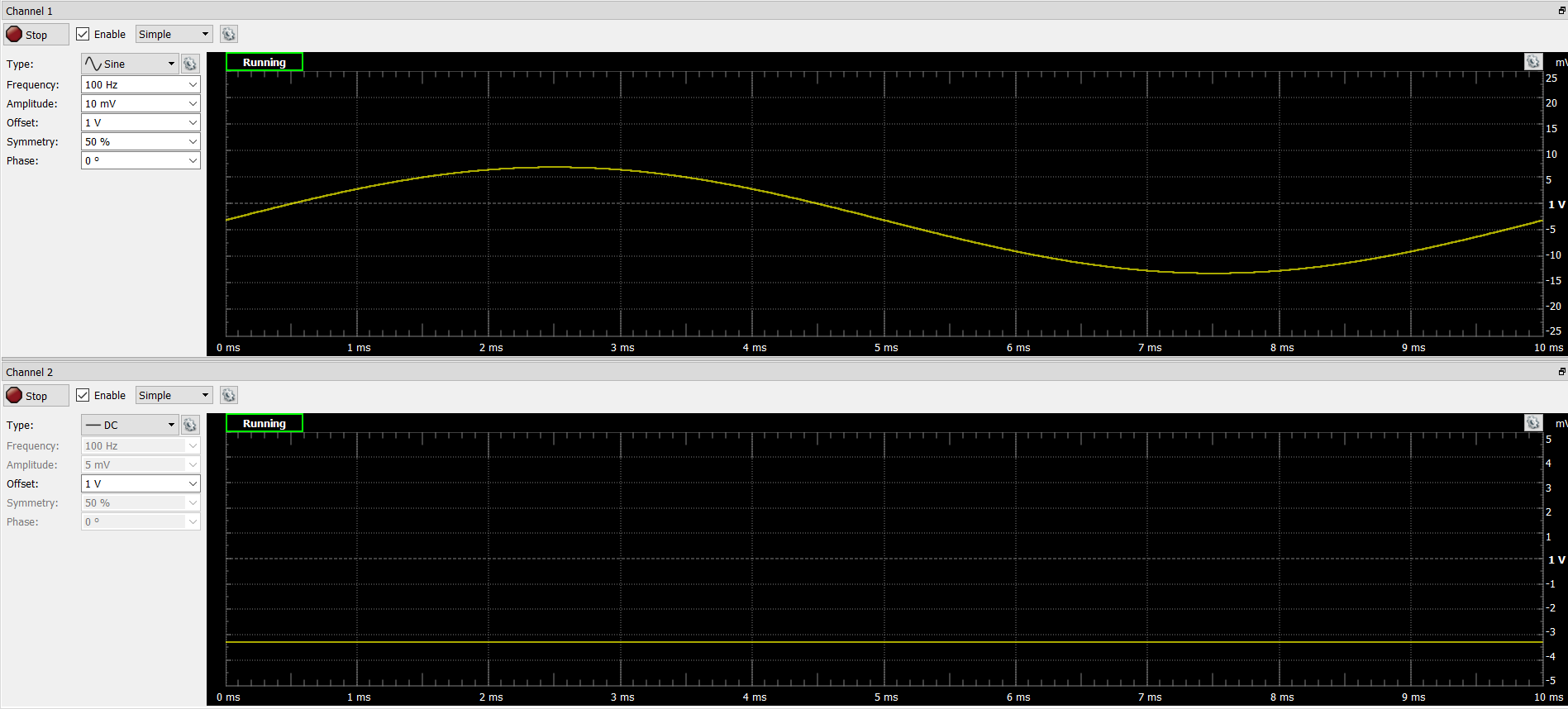
    And the below is the input that i apply on LA and RA inputs. 

  • By providing the above-known sine input of 1Hz and 10mV amplitude with 1V offset to LA.

    And 1V DC offset to RA.

    I am getting this as output.

  • Hello,

    Please help me.

    My work is stuck because of this.

  • Hello Mohin,

    Thanks for showing your input schematic and applied input signal. I'm not sure what your signal source is, but make sure the ground is shared with the ground of the ADS1292R. Then proceed to verify all DC voltages on the chip (AVDD, AVSS, VREFP, VCAP1, DVDD).

    The circuit you are showing for Channel 1 is our recommended circuit for respiration measurements, not for ECG measurements. These components AC-couple the applied input signal, so the 1-V common-mode in your sine wave is not needed.

    For ECG signals, you can leave the inputs DC coupled because you are using RLD. Please refer to the ADS1292R User Guide (Channel 2) for recommended R-C low-pass filter components. The RLD should hold the inputs to mid-supply. You can also turn off the common-mode sensing for RLD (RLD_SENS) and just use RLD as a DC mid-supply for now (just to rule out potential issues).

    With your sine wave test using AC-coupled inputs, you should not have a 2-V differential offset at the ADC output. The 10-M resistor dividers should hold each input pins near mid-supply. Here are some other debug tips:

    1. Configure the device for the internal square wave test signal and demonstrate you can measure that properly
    2. If that works, then increase the sine wave amplitude to something very easy to measure, such as 100 mVp.

    Best regards,

  • Hello Ryan,

    You were right.

    I was trying to measure ECG by setting up the Respiration Circuit.

    I solved the issue. Now I am getting ECG Signal.

    But there seems to be data loss. When I am trying to send data using CC2650MODA BLE.

    Can you help me with that?

    Or should I post a new Question on Bluetooth forums?

  • Hi Mohin,

    Happy you figured it out. Please post new questions in separate threads under the relevant forum.

    Regards,