


Other Parts Discussed in Thread: TMDSEVM6657, OPA625
Hello everyone,
I have already wrote on the forum several times about several things regarding my project. However, I would like to get a general opinion wheather or not I am reasoning several things correctly. I am working on my master thesis and I would really appreciate the help.
I am using the following equipment:
TMDSEVM6657
DAC80504EVM
ADS8920BEVM-PDK
Benthowave Hydrophone with following datasheet:
BII-7186Datasheet SO#1109764.pdf
And three 300 kHz ultrasonic transducers:
https://uk.farnell.com/multicomp/mcusd13a300b09rs/transceiver-300khz-13mm-metal/dp/2362690 .
I would like to use three ultrasonic sensors, which should transmit three different signals. Those signals should be received with hydrophone. The signals shall be modulated chirps of 300 kHz. I would like to use the DSP to generate the signals and then to process the received signals with matched filtering in order to compute distances between the ultrasonic signals and hydrophone.
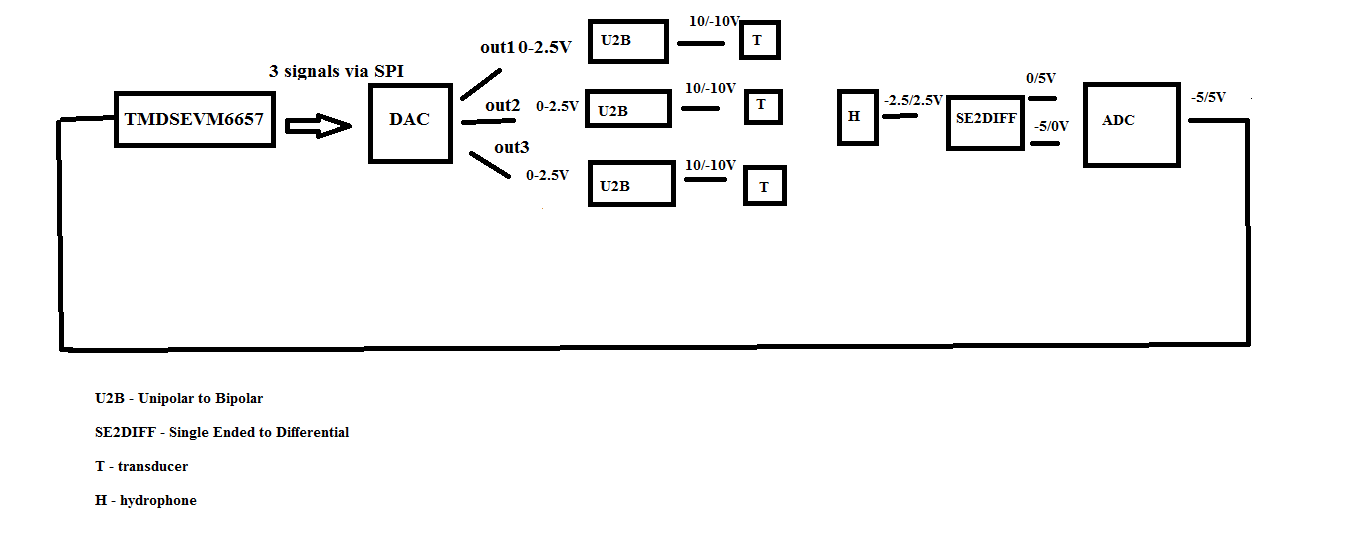
DAC in matter gives output unipolar signals and my hydrophone has built in 30kHz HP filter, therefore I would need to have something to convert unipolar to bipolar signals. I have been advised on the e2e how to design that circuit. Therefore, if output of DAC is 0-2.5V, then the output of the U2B board will be -10/10V. I have designed the circuit using this User Guide https://www.ti.com/tool/TIPD125.
The hydrophone output voltage is 5Vpp single ended. And the ADC has differential inputs. Therefore a circuit for single ended to differential conversion is needed. I also got a suggestion for it from e2e. Using this http://e2e.ti.com/support/data-converters/f/73/p/895475/3310907#3310907 . circuit I would convert bipolar single ended inputs to unipolar differential output. But the output of the ADC would be then again bipolar.
Therefore if I transmit bipolar signals(by sending unipolar signals to DAC, then converting them to bipolar using custom PCB and then driving the sensors with these signals), my hydrophone will have the output voltage of -2.5/2.5V, and the single ended to differential board will give on the output unipolar signals with amplitude 0/5V and -5/0V. The converted signal that I would have as input of DSP will then have the amplitude -5/5V.
Here is a small image of the explained system:
Did I understand all of this well?
My initial idea was to have three LUT in the DSP for the signals that I want to transmit. I use those signals to send them on DAC outputs, but also to match them with received signal using matched filtering. However, if I need to send unipolar signal to DAC and if received signal is bipolar, then that would mean that I should have 6 signals stored as LUT. Unipolar and bipolar version. Do you think that this is correct?
Do you know how can I check if the c6657 will have enough memory space for 6 signals of duration 5ms sampled with 1MHz?
Also, I think that DAC in matter cannot really generate three different signals at the same time. It can update the values of outputs simultaneously via SPI, but with the same value. Therefore, in order to generate three different signals on three outputs I should have some time delay between them?
Please let me know what you think. I am working on all of this without any menthoral support and I having lot of problems with this. E2E is basically my only source help.
Kind regards,
Dejana
