This thread has been locked.

If you have a related question, please click the "Ask a related question" button in the top right corner. The newly created question will be automatically linked to this question.

DAC80504EVM: Generation of three different signals at the same time

Part Number: DAC80504EVM

Hello,

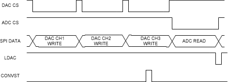
I would like to make a system which generates three different signals at the same time. Currently I am working with DAC80504EVM and as far as I have understood, with this DAC I can either have delayed transmission of three different signals or generate the same signal on all of the DAC outputs, since SPI can provide information about one voltage level at a time. 

Since I want to control this generation with TMDSEVM6657 evaluation board, my current idea is to make a custom board with three one channel DACs, so that I can use all three SPI interfaces. I would use one SPI port  and two McBsp ports from TMDSEVM6657 all clocked with the same clock. Does this make sense? I am not quite sure would it actually be possible to make all of it synchronized. 

If there already is a TI evaluation board with these characteristics, or if you have some better ideas, I would appreciate if you could share if with me. 

Kind regards,

Dejana

  • Hi Dejana,

    You can write to three of the channels in three different SPI commands, but then use a single LDAC pin edge or LDAC SPI command to have the three channels update simultaneously.  Generally, the SPI interface is fast enough to support this.  Can you describe your target output frequency or bandwidth requirements?

    Thanks,

    Paul

  • Hi Paul,

    Thanks for supporting me.

    I would like to generate three CDMA coded linear chirps (300kHz central frequency with 30 kHz bandwidth) of 5ms duration, transmit them and then receive them with receiving transducer connected to ADS8920BEVM. In the TMDSEVM6657 I would like to do three times matched filtering in order to compute time of arrival and distances between each of the transmitting transducers and the receiving one. In order to compute time of arrival I need to somehow track DAC transmission and ADC reception. Generally I intended to use SPI where they are clocked with the same clock and with DMA it would be quite straightforward. But If I use the option that you mentioned I would need to have 3 transmissions for DAC loading (for each of the registers) and then on the fourth one I would have conversion. I am not sure how would I then synchronize DAC with ADC.

    What do you think?

    Kind regards,

    Dejana

  • If the ADS8920 also has a conversion-start pin or register, then you could do the following:

    1. write DAC channel 1

    2. Write DAC channel 2

    3. Write DAC channel 3

    4. Assert LDAC pin and ADC trigger pin at the same time

    5. Read ADC

    repeat.

    Does that work?

  • ADS8920B has a CONVST pin.

    Conversion start input pin. A CONVST rising edge brings the device from ACQ state to CNV state.

    Therefore, I could connect LDAC and CONVST to the same GPIO pin of TMDSEVM6657 but with an inverter for one of them, since LDAC is active low and CONVST is active high. 

    Then I do as you said: 3 SPI transfers for loading the registers, then I send synchronization signal and then I have another SPI transfer to collect new sample from ADC. Then I update DMA buffer with it.

    That sounds like it could work, right? It would affect the resolution of distance measurement tho.

    Thanks a lot, I really appreciate your time.


  • Hi Paul,

    I have been trying to understand my DAC80504EVM and ADS8920B requirements and way of functioning. Could you please support me whether or not the following is correct:

    The datasheet for DAC specifies SPI clock speed of up to 50MHz. If I update the output values of DAC after 3 SPI transmissions, that would mean that I need at least 24x3 = 72 clock cycles in order to update my output. Therefore the update rate of DAC outputs would be 50MHz/72 = approx. 694 kHz. 

    The datasheet for ADC specifies 1MSps sampling rate with 52MHz SPI clock speed. If I have both converters on the same SPI interface with the same clock of approx. 50MHz, it would mean that I would be getting 3x more data from the ADC. So for one sample value from DAC, I get three samples from the ADC. 

    Considering I would like to transmit signals with frequency 300kHz and bandwidth 30kHz, would this be actually useful? 

    I understand that the DAC update rate is not its sampling rate, but I am still a bit confused with whether the output of DAC will be too slow for ADC?

    Please let me know what you think.

    Kind regards,

    Dejana

  • I think you need to consider "coherent sampling".  In this case, it seems like you want the DACs to sample at 300kSPS, are you okay with 1 ADC sample per DAC sample?  If so, you could use the CONVST function of the ADS to trigger the sample.  While the device supports 1MSPS, you do not really need it in this case.

    Consider this:

    There is exactly one sample from the ADC per sample of the DAC channels.  You should space the LDAC pulse from the CONVST pulse to ensure that the output of the DACs are settled before you sample.  In this case the ADC would be sampling the previous DAC update.

    Thanks,

    Paul

  • Sorry if I am being ignorant, but I think that 300kSps on the output of DAC is not satisfying the Nyquist criteria for signals of 300 kHz. Therefore, in this kind of configuration, I would not be able to achieve suitable sampling rate. Am I right?

    Regards,

    Dejana

  • Okay, I thought you were targeting a 30kHz signal, but using a 600kHz sample rate.

    Note that the DAC80504 has a limited settling time.  We specify 5µs to settle from 1/4 scale to 3/4 scale. If you are trying to generate a 300kHz tone, you will see distortion from the output not settling.

    From a programming standpoint, you could still be able to write to the devices in the method I described.  Now you will have 4, 24-bit commands per sample.  So you will be limited to about 500kSPS.  If you absolutely require 600kSPS, then you will need to implement parallel SPI buses.  

    You could use the LDAC pulse as a trigger for the ADC read to keep the two busses synchronized.

  • Okay, but if I reduce the frequency of signal to 100 kHz (which is also suitable), I could perform all of the suggested without much problems regarding sampling rate, right?

    I could use 100kHz chirps for implementing CDMA access (three different transmissions at the same time), and for 300kHz I could implement the TDMA access(three transmissions one after another). Number of samples would be a lot bigger, but then I would not have the problems with sampling.

    Does that sound viable?

  • Yes, that sounds like it could work.  Keep in mind that the SPI interface has other requirements as well, like CS high time and CS to LDAC edge limits, so make sure you are compliant with those as well.  

  • Okay, I think I still don't have enough understanding of the whole SPI DAC ADC communication, I will take that into account. 

    Can you just explain me how do I derive the maximum update rate on the output of this DAC? I thought it was 50MHz/24 + 1/(5us)?

  • This is a great training!

    I have calculated that the update time for this DAC is 23x1/50MHz+ 13ns + 10ns + 15ns = 498ns, and the settling time is 5us. Since settling time is bigger, that means that the max sample rate of DAC is defined by settling time. Therefore 1/5us = 200kSps is the max sample rate. 

    According to this, it is barely enough for 100kHz tone to be generated with compliance to Nyquist criteria. Isn't it a little bit difficult to generate the 300kHz at all?

  • 300kHz is pretty difficult to generate with any buffered precision DAC.  Most DACs are limited by their buffer, which has limited settling time in order to provide better load stability.  Our MDAC (multiplying DACs) or unbuffered voltage output DACS have better settling time because they have no buffer, but it requires the user to select one.  You could look into those as well. http://www.ti.com/data-converters/dac-circuit/precision/products.html#p116=Buffered%20Current;Unbuffered%20Voltage&sort=p1021;desc

    Also, keep in mind that he 5µs settling time is for a very large step, you would really only be limited to the 5µs if you were generating a 100kHz square wave.  If code-to-code transitions are smaller, you could expect settling time to improve. 

  • A bit silly question, but is there a possibility that this EVM board is compatible with another DAC?

  • The DAC80504EVM is only compatible with the DACx0504 family.  That is only 12-, 14-, and 16-bit variants.