This thread has been locked.

If you have a related question, please click the "Ask a related question" button in the top right corner. The newly created question will be automatically linked to this question.

ADS1278EVM-PDK: Service inquiry for ADS1278EVM-PDK

Part Number: ADS1278EVM-PDK
Other Parts Discussed in Thread: ADCPRO, ADS1278, REG104

Hi,

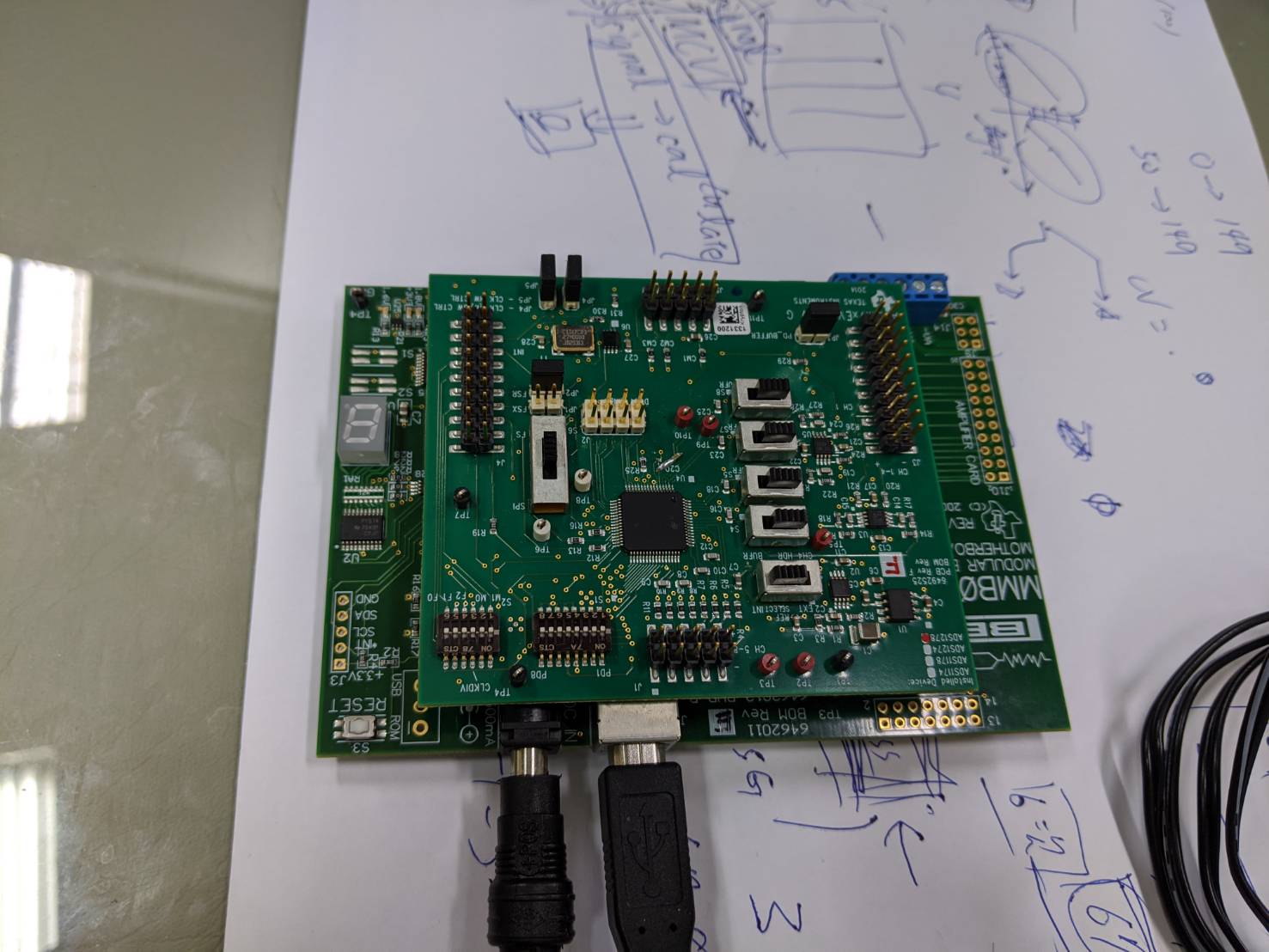
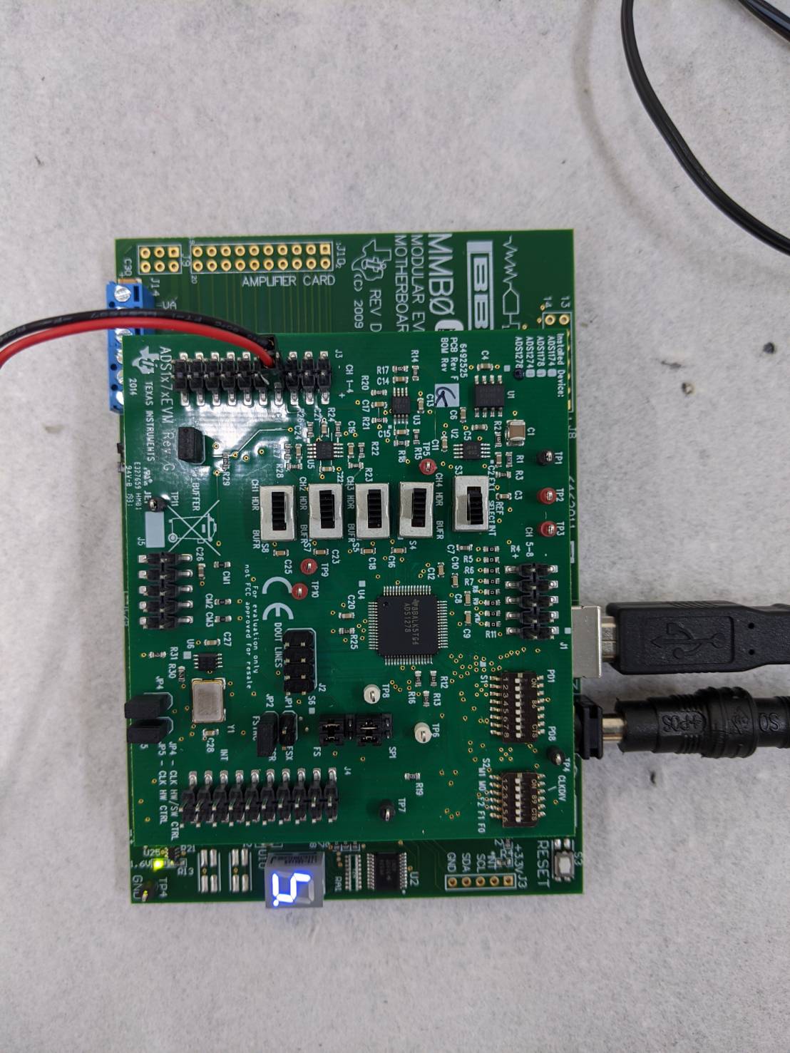
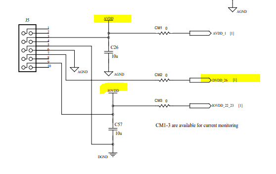
I accidentally input the wrong power supply (12V/1A) to ADS1278EVM-PDK in my experiment.

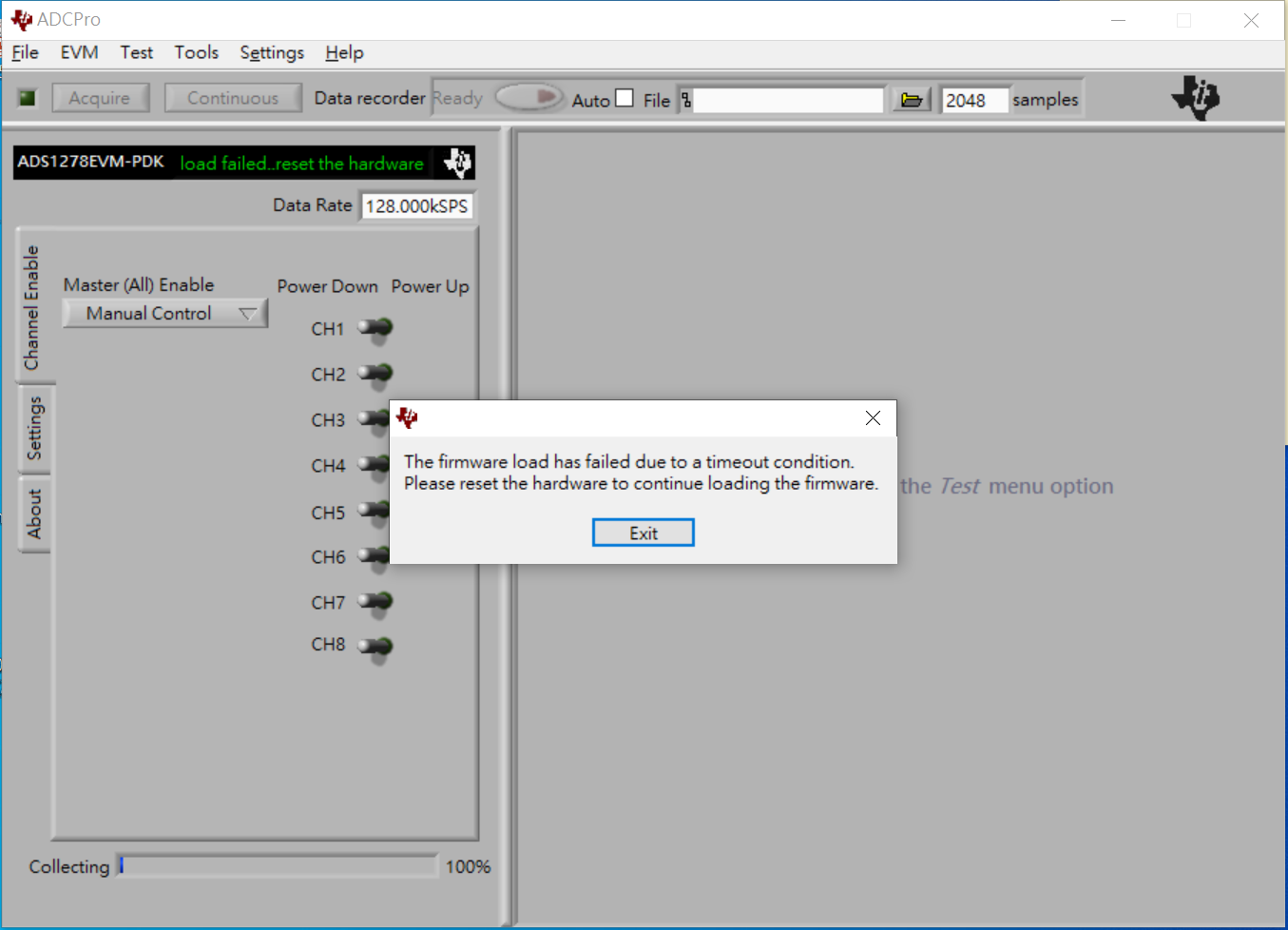
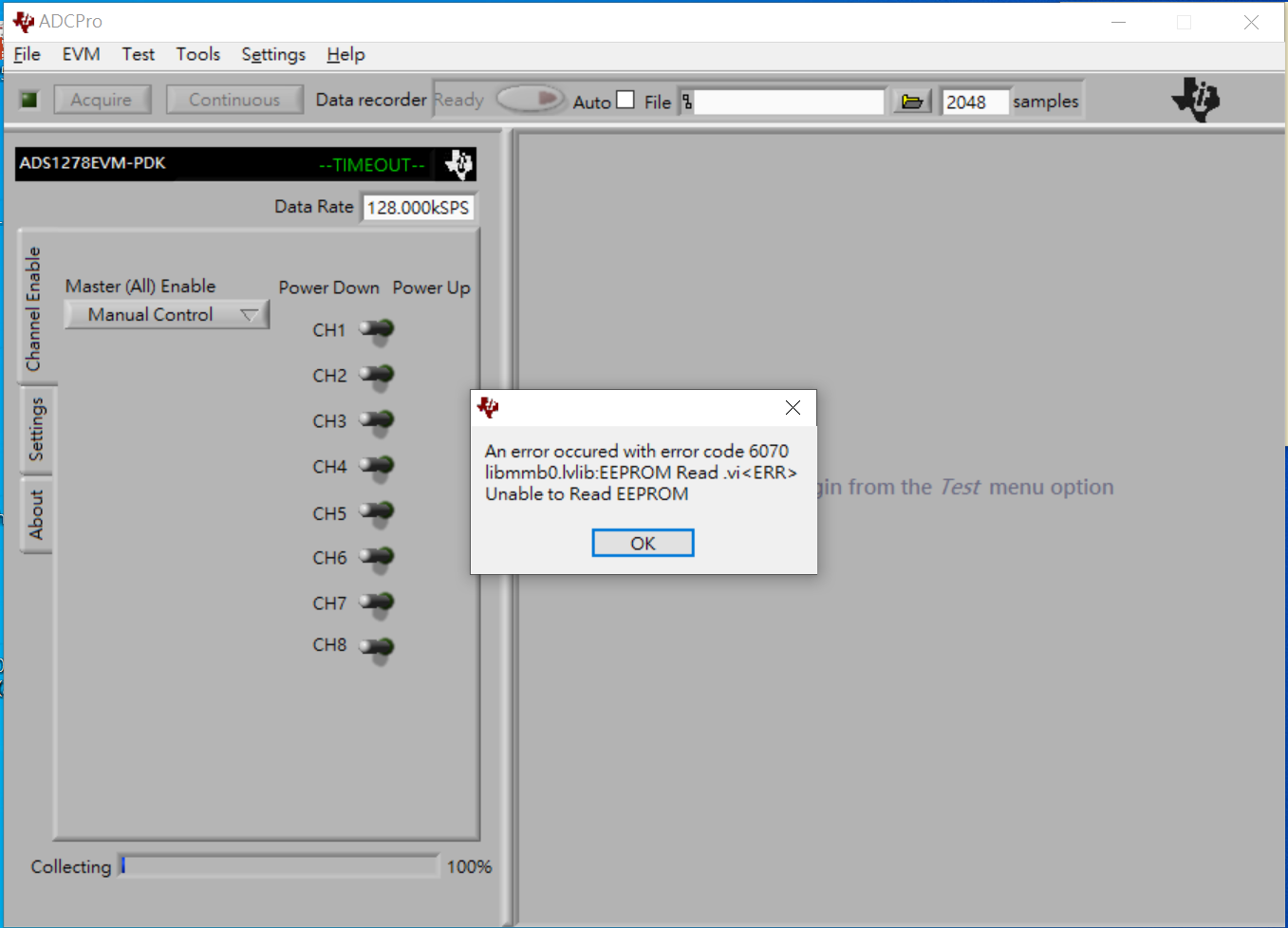
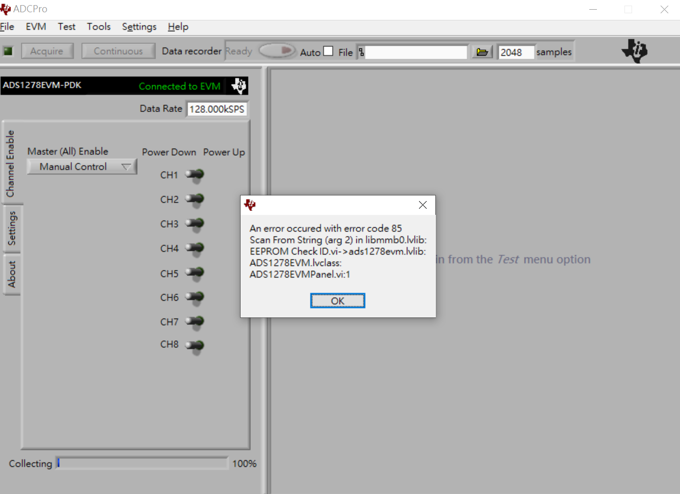
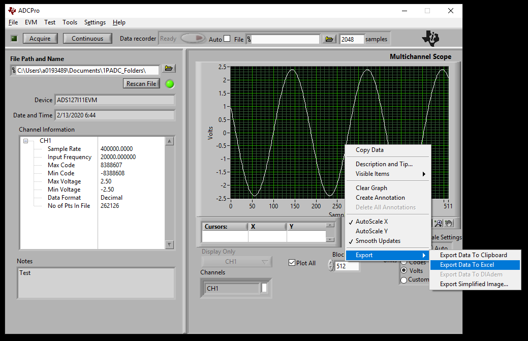
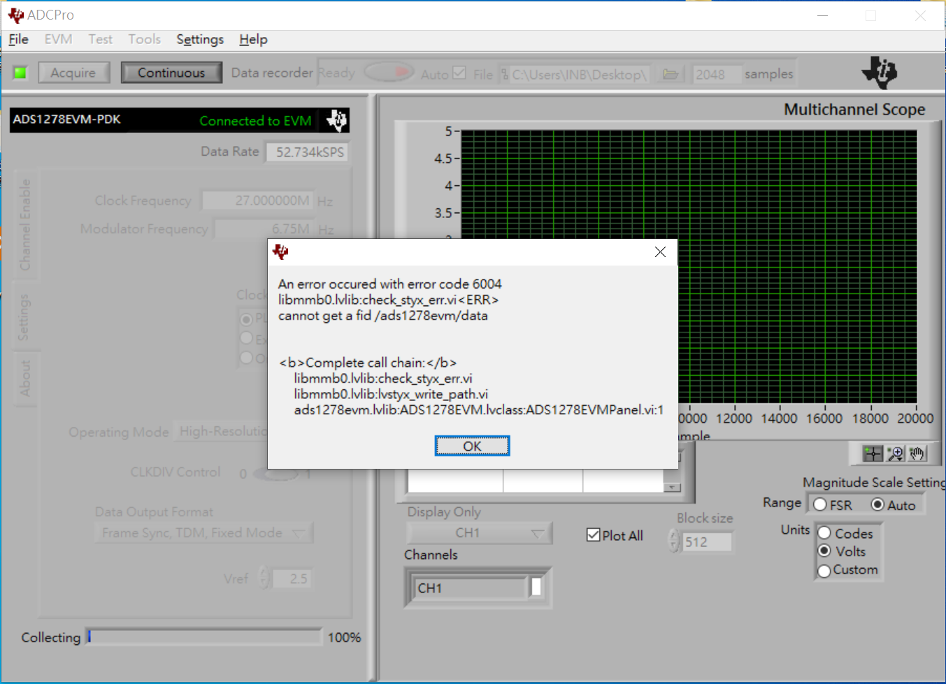
And then it could not work, and ADC Pro show that unconnected hardware.

Even if I used the correct power supply (6V/0.5A) and press reset button, it still not work.

I guess the ADC component was damaged, and i want to send it back to the former factory and repair.

Can you please provide the process or information related to the repair ?

Thank you.

  • Hello,

    Did the EVM work initially until the 12V/1A was connected?  It's likely that the EVM kit may have been permanently damaged by inputting far too high of a voltage on the inputs.  There are not currently any repair options available for damaged/non-functional EVMs although you're welcome to fix it yourself by sampling components from the TI E-Store if you can identify which are non-functional.  Otherwise there are more EVMs available from the e-store:  http://www.ti.com/tool/ADS1278EVM-PDK 

    To help take a quick look at the EVM, could you take an image of the EVM kit with the +6V supplies and USB connections to your computer and also a screen-shot of the GUI when it's not connecting?  

  • Hi, 

    thanks for your reply.

    These feedbacks are for your questions : 

    1. Yes, it can work normally before input 12V/1A.

    2. image for EVM with +6V supplies and USB connections

    3. image for ADC Pro when trying to connect ADS1278EVM but failed

    That is all, is there anything else I need to provide?

    On the other hand, could i buy the chip or EVM for repair?

    Thanks again !

  • Hello,

    Thank you for the additional images and information.  Since the board worked before the over-voltage condition it is likely damaged as initially suspected.  It would be difficult to determine what is damaged in the current system and since the designs are complex with 10's of ICs repairs are not advised and the recommendation is to procure a new EVM from the TI e-store:

    http://www.ti.com/tool/ADS1278EVM-PDK 

  • Hi,

    Okay, i will buy a new one.

    Thank you for the information.

  • Hi,

    I have purchased a new ADS1278EVM-PDK.

    But there was a problem when I used ADCPro.

    There was the figure about error dialog.

    And there was the image for EVM with +6V supplies and USB connections.

    Can you please help me to solve this problem ? Thank you.

  • Hello,

    Since the EVM is having issues reading the EEPROM, try the following to disable it.

    1.    In Windows Explorer, navigate to: C:\Program Files (x86)\ADCPro\plugins\evm\ADS1278 
    2.    Open adcpro_evm.ini in a text editor.
    3.    Change the last line to "EEPROMVerify=FALSE"

    Please let me know if this helps, or if you continue to get error messages.  Also, please verify that the MMB0 board you are now using is the new board and not the one that you originally connected to 12V.

    Thank you,

    Regards,
    Keith Nicholas
    Precision ADC Applications

  • Hi,

    This error message no longer appears, and then ADCPro can work normally.

    But there was another error message when i used ADS1278EVM-PDK to get data in high-resolution mode.

    By the way, I'm sure that i use new MMB0 board and input 6V power.

    This is the figure about error message.

    Thanks for your useful solution, can you please help me again ? 

  • Hello,

    It appears you are trying to use the continuous mode.  I suggest just using the 'Acquire' button to get a fixed number of samples.

    Also, it looks like you are using the Data Recorder feature.  The sample count should match the block size in the Multichannel Scope window.  Another option you can use to save data is to right click on the waveform plot window and select export data.

    Regards,
    Keith

  • Hi,

    thanks for your suggestion,

    but the old ADS1278EVM-PDK could work normally under the same settings as before in continuous mode.

    Why is the new one different from the previous one ?

    Can i use the old MMB0 board with the new ADS1278EVM ?

    The new MMB0 board seems to have so many problems that i can't do the experiment.

    Thank you.

  • Hello,

    The continuous mode depends on the PC keeping up with the throughput and saving data without interruption.  It is likely this would have occurred with the other hardware at some point as well.

    The MMB0 provides the supply voltages to the ADS1278 daughter board.  If the old MMB0 is damaged, and these supply voltages exceed the maximum values for the ADS1278, it could damage the new ADS1278 board.

    If you decide to use the old MMB0 board with the new ADS1278 board, I suggest you confirm the supply voltages are working correctly first.

    Using the old MMB0 and the old ADS1278 board, power this up (even though it does not work), and verify that the supply voltages are correct on the ADS1278 header J5.

    AVDD; should measure 4.75Vmin to 5.25Vmax.

    DVDD; should measure 1.65Vmin to 1.95Vmax.

    IOVDD; should measure 1.65Vmin to 3.6Vmax.  (I think the MMB0 uses 3.3V typical.)

    If these voltages look correct, then you can try using the old MMB0 with the new ADS1278 board.

    Regards,
    Keith

  • Hi,

    but I used the same hardware and software when connecting the new and old ADS1278 EVM-PDK.

    And the old ADS1278 EVM-PDK doesn't need to modify the ADCPro settings, so that i think the new has some differences or problems.

    By the way, i measure both two MMB0 board.

    There are the voltage results.

    AVDD; 6.04 (old) / 4.948 (new)

    DVDD; 1.806 (old) / 1.818 (new)

    IOVDD; 3.291 (old) / 3.301 (new)

    The old one is out of range on AVDD.

    Does it mean that I can't use the old MMB0 board to plug in the new ADS1278?

    Thanks for your support again.

  • Hello,

    DO NOT connect the old MMB0 board to the new ADS1278 board.  AVDD is much too high, and will likely damage your new ADS1278 board.

    Regarding the differences between the old EVM and the NEW, I do not have an explanation.

    Regards,
    Keith

  • Hi,

    i used another computer to connect the new ADS1278 EVM-PDK.

    I also changed the configuration settings about adcpro_evm.ini.

    But ADCPro crashed with another new error dialog when i tried to acquire data.

    By the way, i still used the same settings and mode.

    May I ask how do you test this board to make sure that it has no problems?

    Another thing, can i adjust the old ADS1278 board to make AVDD within the usable range?

    Thanks for your help again.

  • Hello,

    It appears the software driver may not have installed correctly.  You may want to try re-installing all software; make sure you have administrator rights on the PC.

    There is no documented test available for the MMB0 board.  However, if you would like to attempt to repair it, here is the link to the schematic.

    1121.MMB0_Sch_RevD.PDF

    I suspect U5, REG104GA-5, is damaged and needs replaced.

    Regards,
    Keith

  • Hi,

    I don’t think the problem comes from the driver,

    because the previous ADS1278 EVM-PDK does not have these problems under the same computer settings.

    In addition, this board was purchased from Mouser Electronics.

    They said that if Ti can confirm that the product is damaged cause of the abnormal material, we can apply for a return.

    I suspect U5, REG104GA-5, is damaged and needs replaced.

    => Does this mean that we can apply to Mouser to replace the ADS1278 EVM-PDK?

    Thank you.

  • Hello,

    My comment regarding U5, REG104 applies to your old board that had the over-voltage applied to it.  This regulator should have +5V on the output, but you had previously measured 6.04V.

    If using the Continuous mode, these EVM's will eventually have the error code 6004.  This occurs when the Windows PC is not able to keep up with the data transfer from the ADS1278EVM.

    You can use the 'Acquire' mode to gather a block of data up to about 500,000 samples, and then process this data.  The ADS1278EVM is not intended for long term, continuous acquisition of data.

    Regards,
    Keith

  • Hi,

    thank you for your reply,

    But the problem I have now is the newly purchased MMB0 board.

    The old ADS1278EVM-PDK was caused by the input more large voltage, so it cannot be used.

    However, I didn't use the wrong power supply to install the new board.


    If using the Continuous mode, these EVM's will eventually have the error code 6004.  This occurs when the Windows PC is not able to keep up with the data transfer from the ADS1278EVM.

    => But this doesn't explain that the old ADS1278EVM-PDK works in the same configuration, 

    while the new ADS1278EVM-PDK does not work properly.

    Moreover, I have used three computers to test this new board.

    The specifications of computers are all i5 eighth generation, SSD hard drives and 16GB of memory.

    These problems with this new ADS1278EVM-PDK have troubled me for a long time,

    thank you for your help.

  • Hello,

    All of the ADS1278EVM-PDK's will eventually have this timeout error when operating in continuous mode.  I tested one in my lab, and it ran for about 10min, and then stopped working due to the same error that you observe.

    Please note that TI EVM's are only intended to be used as an evaluation of the ADC.  They were not designed or tested to be used as a data acquisition system.

    Regards,
    Keith

  • Hi,

    Thanks for your testing.

    So why does Ti design continuous mode in ADC Pro?

    By the way, if I want to use SPI mode to get data.

    Can I capture data once per second and continue several times?

    And can you provide sample code for SPI mode?

    Thanks again for your detailed reply.

  • Hello,

    Continuous mode is useful to see how repeatable the measurement results are from one block of data to the next.

    The ADS1278 has no limitation on how long you can acquire data; if your hardware supports it, you can continuously collect data with no interruptions.  Or, you can collect a block of data, run an FFT or some other analysis, and then collect another block of data for as long as needed.

    Yes, you can capture data (either a single sample or a block of multiple samples), save it to memory in your host MCU, and then continue several times at 1 second intervals.

    We do not have any SPI code examples for the ADS1278.  Please refer to the Serial Interface Protocols section in the ADS1278 datasheet for details on how to communicate to the device from your host MCU or FPGA.

    Regards,
    Keith

  • Hi,

    got it, thanks for your reply.