This thread has been locked.

If you have a related question, please click the "Ask a related question" button in the top right corner. The newly created question will be automatically linked to this question.

DAC121S101: Output glitches

Part Number: DAC121S101

I am using the DAC121S101 to generate a sine wave.

The sine values are read form a lookup table, when writing the output very bad glitches can be seen on the output as shown below.
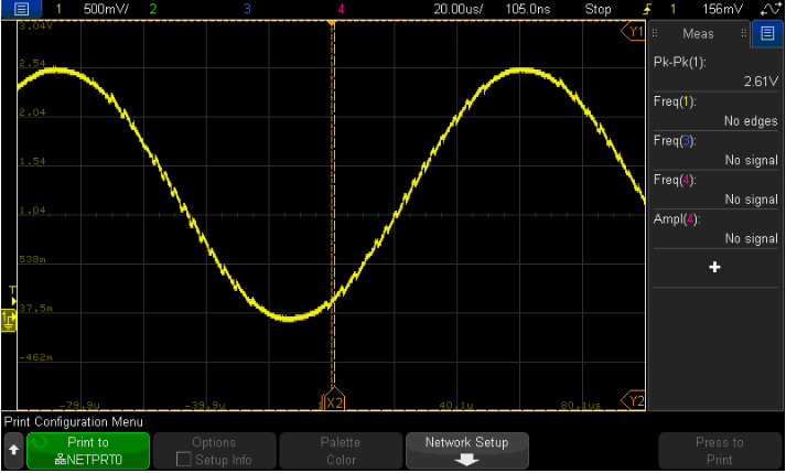
Using an analyzer I viewed the data being sent to the DAC which is shown below against a closer look at some of these glitches, the data does not appear to coincide with the glitch in the output of the DAC so I am relatively sure the error is caused within the DAC and the data being sent is OK. A snapshot of the error with the values being written to the DAC is below.
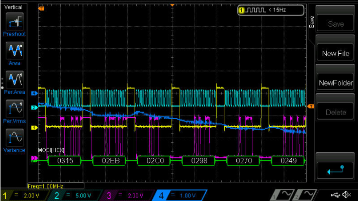
The DAC output here is the blue trace and the hex values represent the data being written to the DAC. these were recorded using the oscilloscope at the DAC pin. It's apparent that the data is continuously decreasing but the DAC output increases at times.

Other points to note, the power supply/reference voltage appears very clean and the SCLK frequency is 20MHz. 

VA is +5V .

The circuit used below.
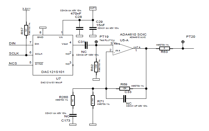
The output was measured at pin 4 of the DAC with capacitor C31 both populated and unpopulated and there was no change in behavior in the two cases.

Any assistance or guidance would be greatly appreciated.

Thanks!

  • Hi,

    Thanks for writing to us.

    What you are observing is the code to code glitch inherent in the DAC (unavoidable consequence of both string and R2R DAC architecture).

    You can eliminate this by having simple RC filter at the output or designing de glitch circuit using a sample and hold.

    I suggest having an RC filter at the DAC output, not a high pass filter as you have shown in your schematics.

    As a check can you swap both components and check for output waveform after RC filtering? Whats the frequency of sine wave you are generating?

    Keep the RC cut off around 5 to 8 times your frequency of interest.

    Let me know the results after you do this test.

    For more information on DAC code to ode glitch please have a look at our educational material below.

    training.ti.com/lessons-precision-dacs-code-code-glitch

    Regards,

    AK

  • Thanks for the quick response.

    I am aware of code to code errors but this seems very dramatic and quite high compared to what I've measured previously using other R2R DACs.

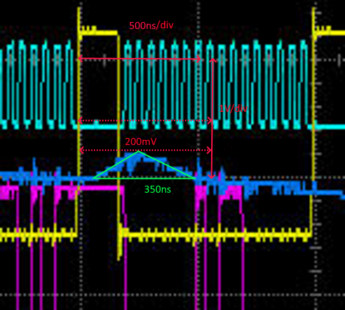
    Looking at the image above and making some rough calculations the peak of the glitch is around 200mV amplitude and lasts for roughly 350ns.For the sake of a very rough calculation for the glitch energy I'm assuming the glitch rises and falls linearly so I've calculated the energy as the area of a triangle (200mV*350e-9 s)/2 = 70nVs. This DAC is specified as 12nVs (at the worst case MSB transition) so even dividing my rough calculation by 4 to account for the very improper mathematics the device would be out of spec.

    Please correct me if my thinking here is incorrect.

    I should have also mentioned that it comes and goes, it is not always present even though the update of the DAC is consistent. I have a video showing the glitches rise and fall over a number of seconds (although the scope triggering could give some inconsistencies here) it is almost periodic. Unfortunately I am unable to attach the video but I presume that if the issue was solely due to code to code transitions the glitches would be consistent and always present?

    The frequency is approximately 6.5kHz

    Unfortunately the application is very sensitive to phase so a simple RC Lowpass may not be suitable but I'll implement it as soon as I can in order to measure the results.

    I will look at implementing a sample hold circuit after the DAC and measure the performance improvements. Unfortunately, due to Covid getting time in the lab can be difficult so this may take a while.

    Thanks again for your help.

  • Hi,

    I was not able to calculate glitch energy from the plot you shared.

    Looking at 70nV/s, the glitch energy seems to be on the higher side than the product specification.

    For a quick check, can you do a dc code change from say 1V to 1.3V and measure glitch energy? I am asking this to do because I want to be sure that device glitch energy is within the specified limits.

    Also to consider is digital feed through. For device, its specified in the datasheet which is generated internally. But significant amount of digital feed-through can come from improper layout as well. Have a check on these as well.

    Regards,

    AK

  • I have attached a very rough image of how I calculated the glitch energy below:

    As the output should be a sine wave (descending at this point, which the digital input values confirm), I'm assuming the error/glitch is the area contained within the green triangle.

    The scope was on 500ns/div and 1V/div so I have estimated the values (I'm currently out of the lab) but the peak is approximately 200-250mV and the width is approximately 350-400ns giving a rough energy figure of between 70-100Vs.

    To test the DAC code to code error I sent a low frequency ramp into the DAC, the DAC values were incremented linearly at 4kHz but the same SCLK frequency was used as before. The output was much cleaner as can be seen below so perhaps the issue is caused by digital feed through more so than code to code or glitch errors.

    The pink trace is the DAC output on the below figure. The curve on the output is due to the AC coupling capacitor, without the cap this response is linear as expected.

    I was assuming the glitch occurred immediately after the SYNC Pulse (yellow in the first image above) as that occurs just as the DAC output is updated (after the 16th falling clock edge) but is it possible that I am seeing artifacts or charging/discharging of the output caused by the SYNC signal? 

    I have ordered an EVM board so I will run some further tests on that in order to run further tests and remove possible layout errors from the equation.

    Thanks again, your input is a great help.

  • Hi,

    In order to be 100% sure its digital feed through, you can test this by slowing down the DAC operation.

    Digital feed-through should proportionately reduce. Also you can try adding small resistors (maybe in the order of 50 to 100Ohms) in the digital lines to reduce the sharp edges.

    Regards,

    AK

  • We have termination resistors on all lines but I will reduce the drive current and slow everything down to see if that helps.

    Thanks again, if that solves my problem I'll be sure to update the thread.

  • Hi,

    Those series termination should be closer to the driving FPGA/micro controller for SYNC, SCLK and SDI signals.

    Let me know how the test goes.

    Regards,

    AK

  • Hi,

    Any update on this ?

     Do you need any more help? For time being I am closing this thread, you can reopen any time if you wish to do so.

    Regards,

    AK

  • Hi AK,

    Sorry for the delay in getting back to you. I've had trouble getting into the lab.

    I think I nailed down the problem, the glitches in the output seem to be caused by me updating the DAC to a new value while it is settling to its previous value.

    It takes about 4us for the DAC to settle from code 0 to code 60, if I update the DAC during this period, I am seeing overshoots/undershoots. There are cases when I am measuring what is certainly code to code glitches which are contributing to the error but I do not believe that this is the primary cause.

    Thanks again for your help.

  • Hi,

    Glad that your problem got solved. Let me know if you need further help.

    Regards,

    AK