


I have a problem when I try to read my ADS1262 register.
After preparing an array with reg values (wreg[20]), (where wreg[0] holds wreg[1] , wreg[1]->reg2 etc...)
...
#define ADS126x_NUM_REG 0x15
uint8_t wreg[20];
...
uint8_t reg_instruction_value=0x41;//WRITE to reg position 1 (reg 0 is ID)
ADS126xSetCS(0); //set CS Pin LOW
while(hspi2.State == HAL_SPI_STATE_BUSY);
HAL_SPI_Transmit(&hspi2,®_instruction_value, 1, 0xffff);
uint8_t reg_blocks=ADS126x_NUM_REG-0x02; //21reg -1, then -1 for ID
while(hspi2.State == HAL_SPI_STATE_BUSY);
HAL_SPI_Transmit ( &hspi2,®_blocks, 1, 0xffff);
for(int i=0;i<20;i++) //write all 20 registers, from 1 to 21
{
while(hspi2.State == HAL_SPI_STATE_BUSY);
HAL_SPI_Transmit (&hspi2, &wreg[i], 1, 0xffff);
}
ADS126xSetCS(1); //to finish writing
ADS126xSetCS(0);
//Reading all registers//
reg_instruction_value=0x20;//Read
while(hspi2.State == HAL_SPI_STATE_BUSY);
HAL_SPI_Transmit ( &hspi2,®_instruction_value, 1, 0xffff);
reg_blocks=ADS126x_NUM_REG-0x01;
while(hspi2.State == HAL_SPI_STATE_BUSY);
HAL_SPI_Transmit ( &hspi2,®_blocks, 1, 0xffff);
for(int i=0;i<21;i++)
{
while(hspi2.State == HAL_SPI_STATE_BUSY);
HAL_SPI_Receive(&hspi2, &AdcRegData[i], 1, 0xffff);
}
ADS126xSetCS(1);
HAL_Delay(1);
ADS126xSetCS(0);
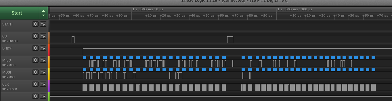
This is a screenshot of my signal:
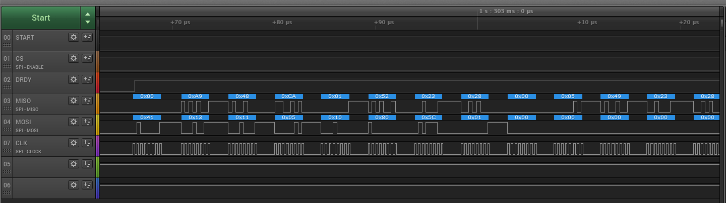
In detail, we can see the write command (0x41 from MOSI) and some regvalus, in particular:
POWER1 : 0x11
Interface: 0x05
Mode0: 0x10
Mode1: 0x80
Mode2: 0x5c ...
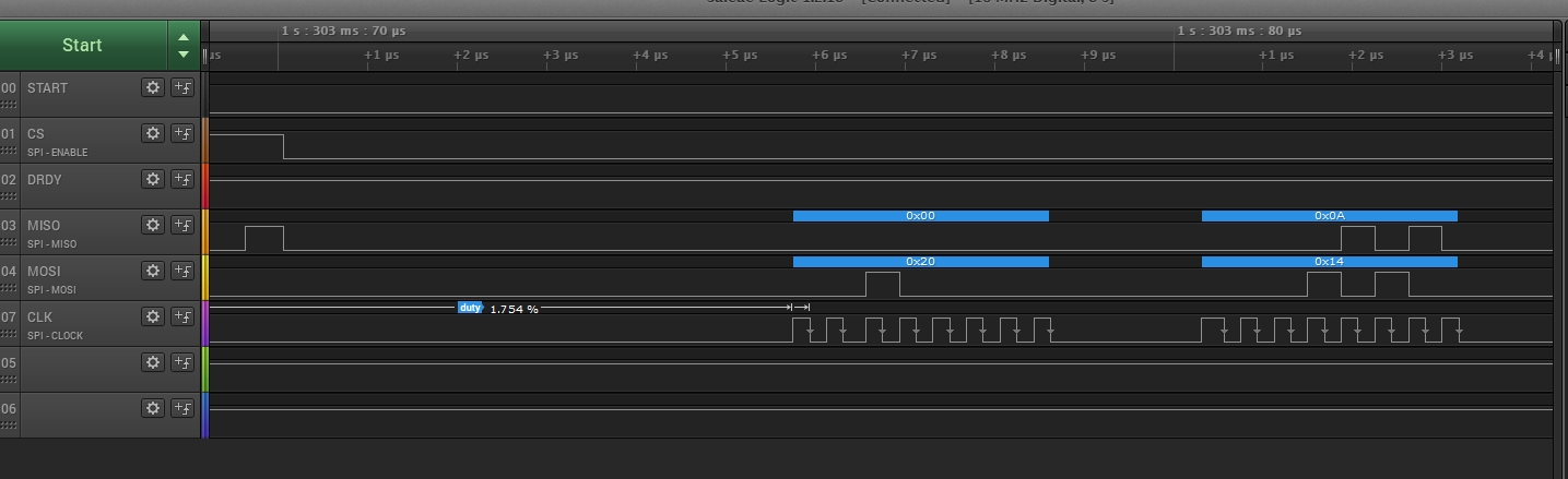
Well, after CS HIGH, I start reading but values are wrong:
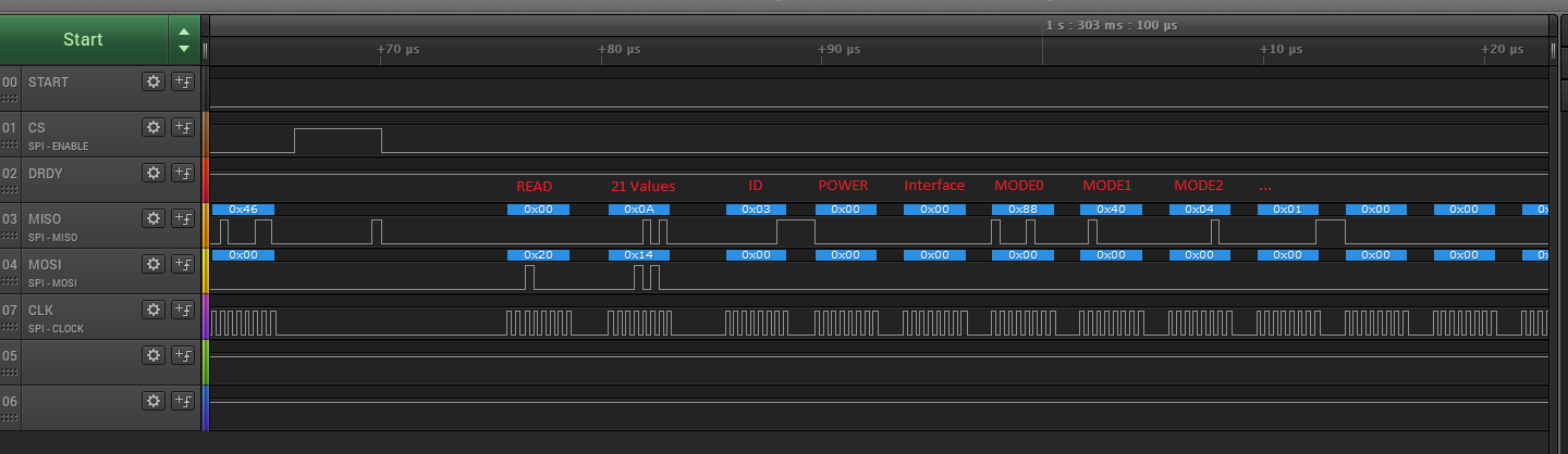
In detail:
Sometimes values are "better", other times are completly wrong.
MY SPI interface is:
static void MX_SPI2_Init(void)
{

/* USER CODE BEGIN SPI2_Init 0 */

/* USER CODE END SPI2_Init 0 */

/* USER CODE BEGIN SPI2_Init 1 */

/* USER CODE END SPI2_Init 1 */
/* SPI2 parameter configuration*/
hspi2.Instance = SPI2;
hspi2.Init.Mode = SPI_MODE_MASTER;
hspi2.Init.Direction = SPI_DIRECTION_2LINES;
hspi2.Init.DataSize = SPI_DATASIZE_8BIT;
hspi2.Init.CLKPolarity = SPI_POLARITY_LOW;
hspi2.Init.CLKPhase = SPI_PHASE_2EDGE;
hspi2.Init.NSS = SPI_NSS_SOFT;
hspi2.Init.BaudRatePrescaler = SPI_BAUDRATEPRESCALER_16;
hspi2.Init.FirstBit = SPI_FIRSTBIT_MSB;
hspi2.Init.TIMode = SPI_TIMODE_DISABLE;
hspi2.Init.CRCCalculation = SPI_CRCCALCULATION_DISABLE;
hspi2.Init.CRCPolynomial = 10;
if (HAL_SPI_Init(&hspi2) != HAL_OK)
{
Error_Handler();
}
/* USER CODE BEGIN SPI2_Init 2 */

/* USER CODE END SPI2_Init 2 */

}
What seems me strange is DRDY, that is HIGH all time long , but how can I put it LOW? Isn't it an output?
Thanks and best regarts,
Mario
