This thread has been locked.

If you have a related question, please click the "Ask a related question" button in the top right corner. The newly created question will be automatically linked to this question.

ADS124S08: Ratiometric - A 200kΩ Reference Resistor...?

Part Number: ADS124S08

I've been doing a little research into a thermistor implementation with the ADS124S08.

The thermistor ranges from [162kΩ @ 0℃], to [370Ω @ 190℃.]

I did some math, and plotted the results as shown below.

Basically, the only way to measure a voltage drop (resistance of thermistor) over 0℃~190℃, is to use the 10µA setting of the IDAC (blue line).
(EDIT: For ratiometric setup w/ current excitation)
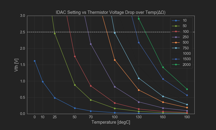
At 0℃, this gives a Vth (thermistor voltage drop) of a little over 1.6V. To get the ratiometric setup, I need a Rref that will give me a Vref > 1.6V. Around 2~2.5V @ 10µA would be best. That means a 200kΩ resistor. I found a 200kΩ ±0.05% resistor on digikey for 30cents in bulk...

But now I have a problem! Namely, the 2.0V drop across Rref, and 1.6V drop across the thermistor is "impossible" with AVDD = 3.3V...

If I used the internal reference, now I have the ±5% IDAC accuracy issues...

Is there a good recommendation on how to go about measuring such thermistors? Should I be looking at voltage excitation instead for this thermistor? Just slap on a series resistor and pray my voltage line has no noise?

  • Hi Darren,

    With the given constraints in the measurement you would require AVDD equal to 5V.  If the AVDD is 3.3V and if you use the internal reference for the ADS124S08 and also voltage excite the thermistor, the measurement would still mostly be ratiometric. The same would be true if you used the AVDD supply as both excitation and as an external reference, but depending on how quite the supply is the noise may be large negating any positive effect of more range.

    Best regards,

    Bob B

  • Hi Bob, thanks for the hint. For the setup, I think it will be very difficult to switch to AVDD = 5V, but I see your point...

    I was also just looking up parallel resistance, and it looks like I could keep the "voltage drop across Rp and Rth" low enough, and use the PGA instead...while also making it easier to get 2.5V Vref...

    Would parallel resistors be a way to go? 

    Sorry if these questions are overly newbish :)

    Darren

  • Hi Darren,

    Parallel resistance is used to linearize the transfer function of the thermistor output instead of using a LUT or the Steinhart-Hart equation to calculate the temperature.  Some thermistor manufactures had programs you could use to calculate the parallel resistance. Here is a link that describes the calculation:

    https://www.edn.com/linearize-thermistors-with-new-formula/

    I'm not sure in the end how much you will gain by using a parallel resistance.

    Best regards,

    Bob B

  • Hi Bob, thanks for the info again. (Equation was helpful)

    Below I summarized the thermistor (PT3-51) with different parallel resistances. It was interesting to see how the resistance is "linearized" by adding a parallel resistor...

    Basically, I was thinking the parallel resistor not only helps with linearity, but also helps to reduce the overall "voltage drop", or differential input voltage the ADC sees when using the IDAC, because the equivalent resistance is lower (R = 1 / ((1/R1) + (1/R2) ...)), For V = IR, where R goes down, V goes down.

    This has been my thought process:

    If I set the IDAC to 250uA, and the Rref to 7.5kΩ, I would get a reference voltage of around 1.88V.

    With a parallel resistance of 3.3kΩ(see red line from below figures), this keeps the largest total voltage drop across Rref and the Rth/Rp to under 2.7V, plenty of headroom for AVDD = 3.3V.

    At this IDAC, I also see a voltage drop of around 0.81V across the equivalent resistance at 0℃.

    If I set PGA = 2, then this is like +1.6V, which is less than +FS (Vref = 1.88V), and within the allowable range.

    This gives me around 43% ADC FSR, and for a ΔT of 190℃, gives me around 0.00004℃/Code.

    Next, from the DS Table 1, I see the noise at DR of 100SPS to be 5.8µVpp, and the 24-bit ADS124S08 LSB is around 224nV for Vref = 1.88V.

    With this, I can calculate around 26 codes (224nV * 26 is about 5.8µVpp) that are "noisy codes".

    If I ignore these "lower" decimal digits in the output code, then I can resolve temperature to 0.0003℃.

    Assuming a safety factor for other sources of noise, I should be able to resolve temperature to better than 0.1℃...yes?

    (linearity, gain/offset errors, thermistor variation and non-ideal LUT, etc create an offset from the actual temperature that can drift/change over conditions, and I am not considering that atm...but still hoping to get better than 1~3℃)

    Is my thought process so far on track?

  • Hi Darren,

    I didn't completely go through all of your calculations, but your thought process is on the right track.  However there are a couple of calculations I want to point out.  One is with respect to the noise table numbers.  You are using the sinc3 filter at 100sps with table 1.  If you are going to cycle through the mux you probably would want to use the low-latency filter.  The sinc3 filter requires 3 conversions for settled data in the digital filter for the first conversion and then 100sps after that.  Each time you change the mux you would have to complete 3 conversions before you would see conversion results.  If you use the low-latency filter the conversion time reduces significantly following a mux change.  I would suggest looking at table 3 for the low-latency noise numbers.  At a gain of 2 for 100sps the peak-to-peak noise is 10uV.

    Second calculation I wish to point out is the LSB size relative to full-scale range.  If Vref is equal to 1.88V, then the full-scale range at gain of 1 is +/-1.88V, but at a gain of 2 it is +/- 1.88V/2.  The LSB size computes to approximately +/-Vref/Gain/(2^24) which for a gain of 2 and 1.88V Vref would be 112nV.  The codes of noise in this case with 10uV p2p noise would be around 89 codes (3.32 bits).

    When making calculations relative to full scale, 24 bits is for +/-Vref range.  If you only consider the positive full-scale then this would be 23 bits. If you have 23 bits, but three bits are noise, then the measurable resolution lowers to 20 bits.  Your total temperature resolution is relative the maximum resistance of the thermistor/Rp combination relative to the resistance value. 3.3k *2 (gain of 2) is 6.6k/7.5k or 88 percent of the available codes.  If the resistance range was entirely linear, then the number of codes available (2^20) times 88 percent would give you the measurable codes.  Assuming I calculated this correctly myself, there would be 922746 total counts available at a gain of 2.  This would result in 0.000038 per deg C resolution and like I said previously this is if the resistance throughout the range was linear.

    In essence you are on the right track.  Consider though the measurement is ratiometric relative to the reference resistor value and not a voltage when calculating the temperature numbers.

    Best regards,

    Bob B

  • Hi Bob, 

    This really helps get me up to speed when discussing these topics with customers. Thanks.

    I've attached a document with some hand calculations. If you could take a quick peek and see if I'm getting the concepts, that would be great.

    Especially at the bottom, regarding the noise-free bits and resolution. I am getting 0.001℃ resolution. (This will vary with Rref/Rp/Rth variations from ideal, so for now just the basic calculation with ideal values)

    ADC_Thermistor_Resolution(1).pdf

  • Hi Darren,

    Keep in mind that the value of the code is not in degrees C or V, but rather resistance.  If the resistance is linear, then you can reverse calculate the approximation they way you have shown.  However, the total counts of 2^17.5 is for 185,363 for the full-scale range, but you will only be seeing 88% of that range which reduces the usable counts to 163,120 for 0 to 190 deg C.  This alters the value of the code to 0.00116 deg C for a linear resistance through the measurable temperature range.

    If there is non-linear deviation the measurement may change to something much different than the expected and that is why you need to use the true resistance values and perhaps use a piece-wise calculation or lookup table to calculate the temperature.

    Best regards,

    Bob B