This thread has been locked.

If you have a related question, please click the "Ask a related question" button in the top right corner. The newly created question will be automatically linked to this question.

ADS131M08: SPI command question

Part Number: ADS131M08


Hi,

There is a couple of questions for SPI command.

1. If write only #3, #4 registers, send 0110000110000001 + #3 register value+ #4 register value and get the response which is 0100000110000001 in next /CS. Is it correct?

2. If Ch0,1 is disabled, is DOUT started from Ch2? or from Ch0 but Ch0, 1 is dummy?

3. If /CS time is not enough to Ch0~Ch7 DOUT time, does DOUT send data during /CS?

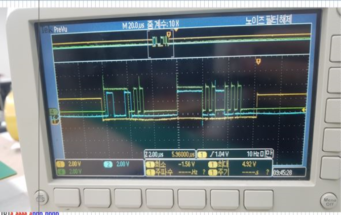
4. Below is SPI signal in EVM.

Command is CH1 EN --> disable

Picture1, Yellow is /CS, Green is DOUT, Blue is DIN

Picture2, Yellow is SCLK, Green is DOUT, Blue is DIN

What is 00000000 of 3rd, 6th byte in DIN?

Thanks.

  • David,

    I'll just answer the questions in order.

    1. WREG starts with 011 then for, you would next have 000011. If you're only writing to two registers, then the n+1 number is 2, so you would send n=1 which would be 0000001. To put this all together you would use: Binary: 0110 0001 1000 0001 (in Hex this is 6181). Then you would send the register values for #3 and #4. There is some zero padding to make sure that the data is sent in the proper word size.

    As a response, you would see this in the next frame on DOUT. The response would start with 010. Then 000011, then then 0000001 (2 bytes minus 1).

    2. If channels CH0 and CH1 are disabled, the data frame still clocks out data in the space for CH0 and CH1. However these data bits should be 0s.

    3. I'm not sure I understand this question. /CS activates the SPI. If you are in the middle of clocking out data and /CS returns high again, DOUT will go Hi-Z. Even with SCLKs going, DOUT will not be transmitting.

    4. First, here is the original sequence for reference:

    Looking at this command, this says WREG, starting at address #3, for 1 register. This is followed by a byte of zero padding. Then the data sent to the register is FE0E. The last byte of zeroes is also zero padding. Note that the SPI communication is made up of communication frames, and each frame has several words. For the default, the word size is 24bits.

    If you look at the above, there is one communication frame and two words. The words are each 24 bits as set by WLENGTH [1:0]. The 24 bit words size is default.

    For communication, I would review the SPI section in the datasheet:
    For SPI Frames: Section 8.5.1.7 (page 31)
    For SPI Communication Words: Section 8.5.1.8 (page 32)

    Joseph Wu

  • Hi Joseph,

    If I want to read the measurement data without any read and write in register, can I get the measurement data with below sequence?

    When data ready, make /CS low, DIN is floating or all zero and get the data from DOUT after 24bits response.

    Is it correct?

  • David,

    I'm sorry I'd forgotten about responding to this question. 

    If you're not reading and writing to the device, you can just use a NULL command to read the data from the device. This would still start with the null command (all 0s), with enough SCLKs to receive the command response, the data from the channels, and then the CRC word.

    Joseph Wu

  • Thank  you very much Joseph