This thread has been locked.

If you have a related question, please click the "Ask a related question" button in the top right corner. The newly created question will be automatically linked to this question.

CCS/ADC128S102: ADC128S102-TMS570LS0432 connection settings

Part Number: ADC128S102
Other Parts Discussed in Thread: HALCOGEN

Tool/software: Code Composer Studio

Hello,

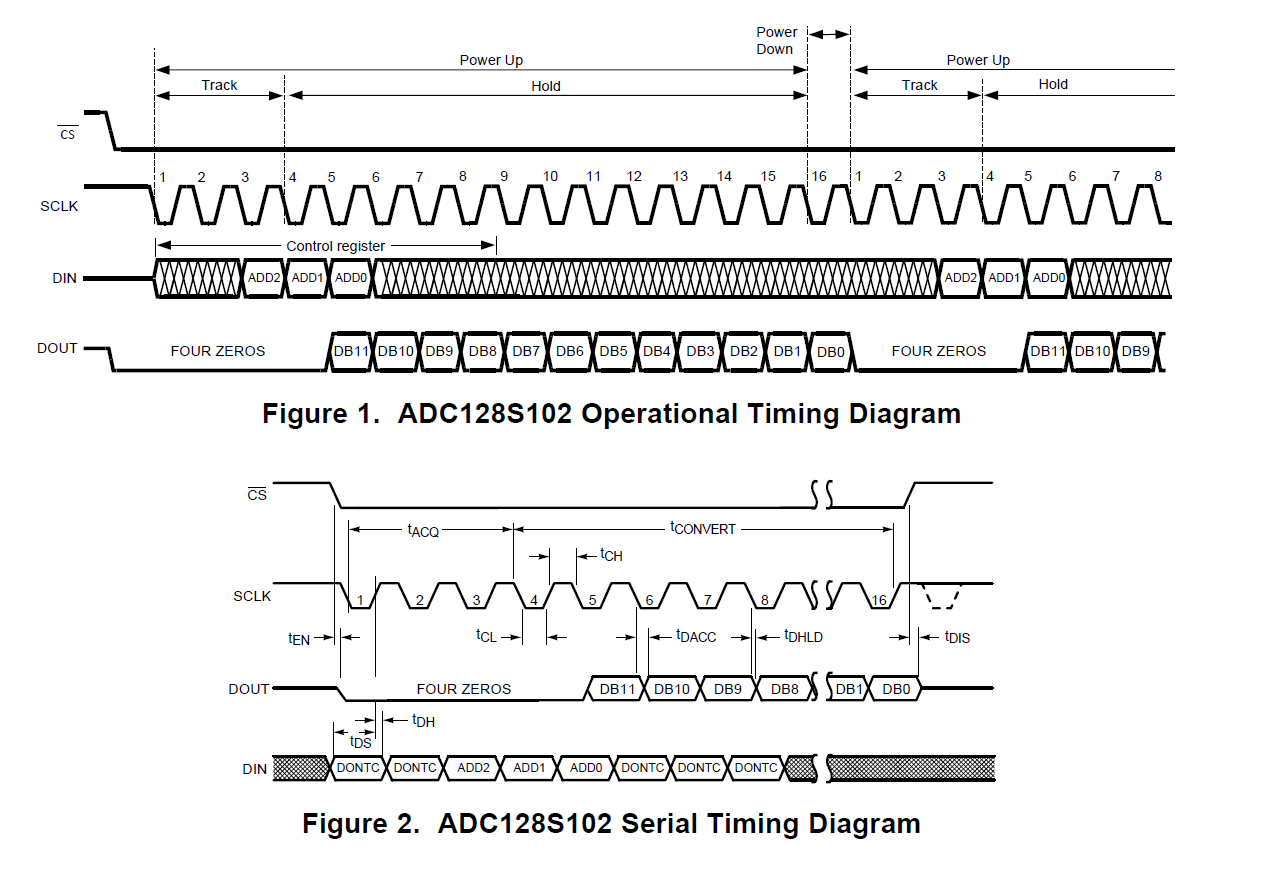
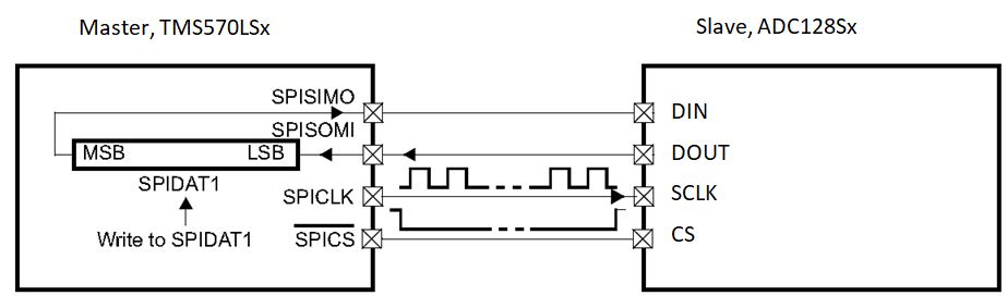
I want to communicate ADC128S102-TMS570LS0432 lauchpad with spi communication.What kind of settings I have to make in Hercules?

In datasheet I didnt found any spi mode for ADC, clock frequency 8MHz to 16MHz,

There is something different can anyone offer.

I am new at this kind of settings for this reason please help me for the settings.

  • Hello,

    If you need help with working Hercules or the launchpad, I will notify that team of your thread.

    As for the ADC, I suggest working from the timing diagrams, as this provides a visual of the digital communications. you will need to connect CS, SDI, SDO, and SCLK from the devices to the micro. I also suggest using a scope to visually check the digital communications, this will provide a visual check to debugging firmware and confirm firmware is heaving as expected.

    CS falling edge initiates the conversion, SCLK controls the sampling rate as well as the throughput rate.

    The device enters track mode under three different conditions. in all three the output changes in the falling edge of SCLK, and should be read on the rising edge.

    1. CS goes low with SCLK high. The ADC enters track mode on the first falling edge of SCLK.

    2. CS goes low with SCLK low. The ADC automatically enters track mode and the falling edge of CS is seen as the first falling edge of SCLK.

    3. CS and SCLK go low simultaneously and the ADC enters track mode.

    Regards

    Cynthia

  • Hello,

    I wrote wrong to my description about the ADC128s102.

    I want to know about HALCOGEN settings for writing code and communicate between adc128s102 and tms570ls432.

    Please help me for this topic.

    Regards.

    Hasan

  • Hello Hasan,

    To use TMS570 SPI module, please enable the SPI driver under "Driver Enable" in HALCoGen"

    SPI is a synchronous, full duplex master-slave-based interface. The data from the master or the slave is synchronized on the rising or falling clock edge. Both master and slave can transmit data at the same time. The SPI interface can be either 3-wire or 4-wire ( or 5-wire, please refer to TMS570 datasheet. ADC128S102 supports 4-wire (SCLK, nCS, DIN, DOUT).

    To begin SPI communication, the master must send the clock signal and select the slave by enabling the CS signal (active low). SPI is a full-duplex interface; both master and slave can send data at the same time via the MOSI and MISO lines respectively. During SPI communication, the data is simultaneously transmitted (shifted out serially onto the MOSI/DOUT bus) and received (the data on the bus (MISO/DIN) is sampled ). The serial clock edge synchronizes the shifting and sampling of the data. The TMS570 SPI interface provides the user with flexibility to select the rising or falling edge of the clock to sample and/or shift the data. ADC128Sx uses clock mode 0 (different from TMS570 mode 0), so please use clock mode 0 for TMS570 side (data is shifted at rising edge, and sampled at falling edge).

    ADC128x clock frequency input is 8Mhz to 16Mhz. You can select SPI baudrate in HALCoGen between 8000KHz to 16000KHz. 

    ADC128x uses 16-bit char length. Please use 16-bit charlen in TMS570LSx side too.

    Then, save project, and generate code.

    Please refer to SPI example in HALCoGen Help Topics.