This thread has been locked.

If you have a related question, please click the "Ask a related question" button in the top right corner. The newly created question will be automatically linked to this question.

ADS54J20EVM: The calculation of equal input impedance

Expert 1055 points
Part Number: ADS54J20EVM

Hi Jim,

   I still have some doubts,please help me confirm this:

   1, In the section 9.2.1.1,as long as i choose the frequency of input signal,i can select the corresponding RC value and calculate the ZIN

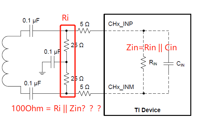
   2,At this step i’m not sure whether to use the R&C value  to calculating by theR&C off-chip and ZIN

  For example,if the requirement of design  is 100Ohm input and the frequency is 100MHz,then we can  confirm the RIN is 900Ohm and CIN is4.75pF,so the ZIN equal to RIN || CIN and the value is 244Ohm。

  Therefore in order to get the 100Ohm input impedance the R value is 169Ohm(100Ohm = 169Ohm || 244Ohm),is that correct?

  • Suy,

    This would be true if you were driving with a DC circuit. This is not true with the image you show as it is AC coupled.

    Regards,

    Jim

  • Jim,

       So what you mean is setting the RC vaule  for AC coupled only according the curve of figure 133&134?

  • Suy,

    No. DC coupled circuit. From the data sheet:

    "When designing dc-driving circuits, the ADC input impedance must be considered. Figure 133 and

    Figure 134 show the impedance (ZIN = RIN || CIN) across the ADC input pins".

    The ADC parameters should be taken into consideration when determining the overall impedance of your input pcb traces.

    Regards,

    Jim