This thread has been locked.

If you have a related question, please click the "Ask a related question" button in the top right corner. The newly created question will be automatically linked to this question.

ADS131M04EVM: ADS131M04EVM

Part Number: ADS131M04EVM
Other Parts Discussed in Thread: ADS131M04

Just received the ADS131M04EVM, connected it to a CT and AC transformer and have captured numerous appliance load profiles at 4k,8k,16k,32k sps.   Works GREAT!    I would now like to read the board with my Raspberry PI and a Python program that I found on the web instead of my PC.    Using a Python program gives me much more flexibility to do things like threshold recording to compress the raw data.   I see the pin jumper block where I can connect my Raspberry PI to the SPI interface and to ground, HOWEVER, I don't see any pin jumper to connect the 5V to the board other than the large special connector on the bottom of the board.   How do I power a "stand alone"  ADS131M04 board from a Raspberry PI?

Would appreciate some insight, thanks...   Mel

  • Mel,


    Originally, I would have suggested using a power supply to connect to TP1 and TP2 on the upper right hand corner of the schematic. This would be for a direct connection to AVDD and DVDD, the analog and digital power supplies. Note, the ADS131M04 doesn't run on a supply as large as 5V. The maximum supply is 3.6V.

    If you don't have 3.3V supplies handy, you'll likely have to solder a connection to R46 and drive the 5V to the LDO. Then connect the output of the LDO to both AVDD and DVDD. There are connections throughout the board, including the unused connections on the bottom intended for a launchpad.

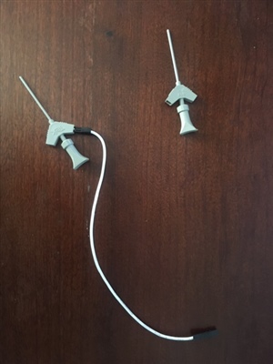
    However, I believe that the raspberry pi does have 3.3V outputs, and you would need a clip connector to get to TP1 and TP2 that looks something like this:

    Joseph Wu