This thread has been locked.

If you have a related question, please click the "Ask a related question" button in the top right corner. The newly created question will be automatically linked to this question.

ADS1278: DOUT lines all Low - Issue with second board

Part Number: ADS1278
Other Parts Discussed in Thread: THS4521

I had already posted about this issue I had with 1 out of 10 new revision (REV D) boards here https://e2e.ti.com/support/data-converters/f/73/t/896978

I originally thought I just got a bad chip on the 1 board, and sent it back to the assembly house to have it replaced. Got the board back and it is working ok so I had closed the issue.

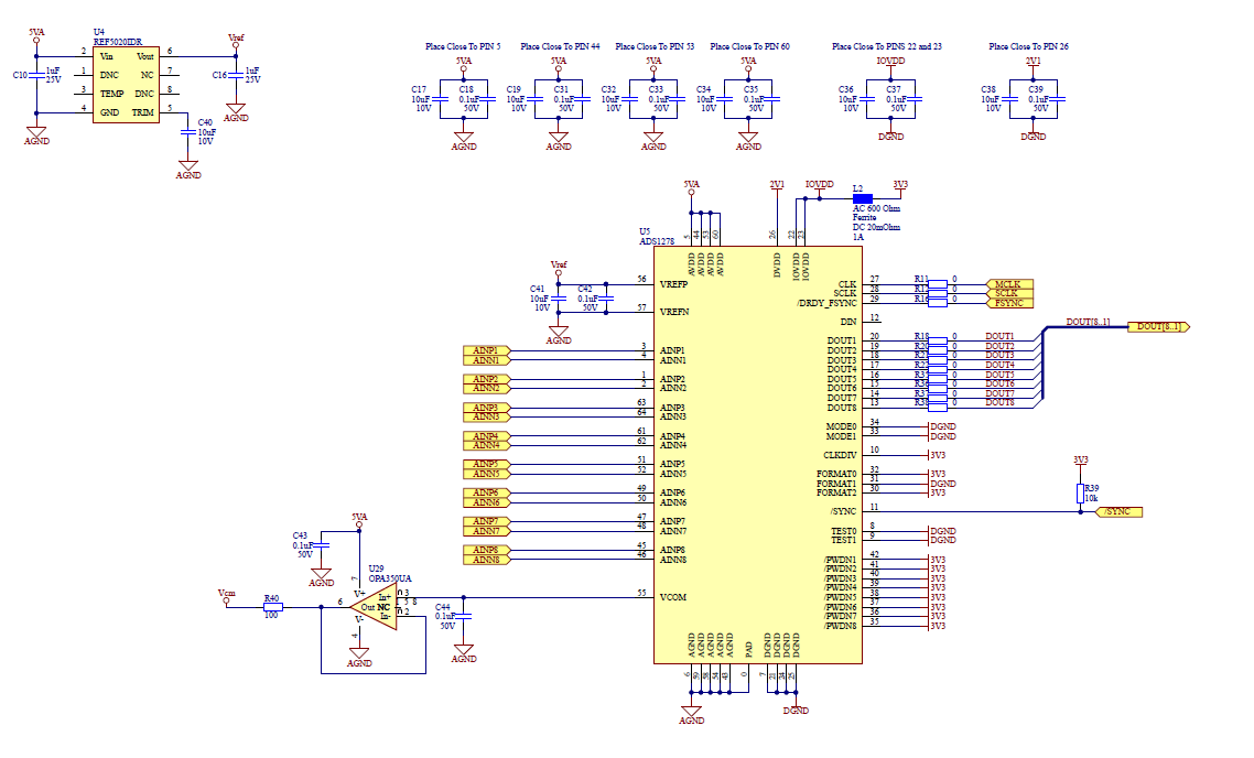
Now on an additional board, which had been working fine, the same issue has occurred where all the DOUT lines are low. Nothing changed in the design or layout with the ADS1278 from REV C to REV D, and there are REV C boards that have been running for over a year without any issues.

I do connect AGND and DGND with a ferrite bead close to the ADC. When I measure the potential between AGND and DGND it is only ~20-25mV which is well within the specs, so I wouldn't think that is the problem, and the grounds are connected this way on the REV C boards which have never shown this issue.

Any additional help would be appreciated.

Thanks,

Eric

  • Hello Eric,

    I assume you have checked all supply voltages and clocks (CLK, FSYNC, SCLK), per your previous post.

    This could be a power-up issue.  If the Start-Up sequence is not met in Figure 84, the internal power-on reset may not work properly.  You can effectively reset the device by toggling the /SYNC pin if this is the case.

    If the device and board have been operating properly for a period of time, and then the device stops working, this could be due to a latch-up event.  As you noted, there is a ferrite between AGND and DGND.  We do not recommend placing any impedance between these grounds, and for robust operation, AGND and DGND should be directly connected to the same ground plane beneath the IC.

    I have also assumed that you can get the device working again by power-cycling the board.  If not, then the device may be permanently damaged.

    What amplifier are you using to drive the inputs?  Is this amplifier powered from the same 5V supply as AVDD?  If not, then an over-range condition during normal operation or during power-up could also cause the device to latch-up as well.

    Regards,
    Keith Nicholas
    Precision ADC Applications

  • Hi Keith,

    Yes, I have checked all the supply voltages and clocks. Everything looks good there. The ADC is even outputting 2.5V from Vcom. I have tried toggling the /SYNC pin, but that did not get the device running again. Power cycling the board does not help either. So as you noted the device may be damaged. 

    I am using the THS4521 as the input buffer amplifier. The inputs to the amp are differential from Analog MEMS Microphones off board. The amp is powered from a single supply which is the same 5V as AVDD.

    Attached are screen captures of the schematic sections of the ADC and Buffer Amplifier. 5VA, 3V3, and 2V1 are supplied from TPS7A9001 LDOs.

    The first board that had this issue with the ADS1278 failed "out of the box" from the manufacturer. So I had just figured we had a bad chip. This one was working fine and now has failed. Do you think we just got a bad batch of ICs and it just took longer for this one to fail? The schematic sections below are the same as the REV C design, which we have not had this issue with.

  • Hello Eric,

    I do not see any obvious problems with your schematic, but here are some recommendations.

    1. DIN should not be left floating.  For Frame Sync mode, connect DIN to GND.

    2. Remove ferrites L2 in IOVDD path and the ferrite between AGND and DGND.  Replace with 0ohm resistors.

    Assuming the device is damaged, the question is then what caused it.  Many customers have seen lockup and damage to the ADS1278 when not connecting AGND and DGND directly to a common ground plane at the device.  In your case, a large current spike induced by an ESD or other over-voltage event, with fast rise and fall times, can easily push the AGND and DGND apart by more than 300mV for a short period of time.

    Another possible cause is during power-up.  Some older generation regulators can have a large overshoot during power-up with light loads.  You may want to check the voltages on all of the supplies during power-up to make sure none exceed the maximum voltage specs of the device.

    Regards,
    Keith

  • Hi Keith,

    Thanks for the feedback.

    The 3V3 supply is from a switching regulator and supplies the 3.3V to all the digital circuitry on the board. I had L2 in there to try and reduce noise from the switching. Would you suggest using a separate LDO to supply the 3.3V for IOVDD?

    I checked the supplies during power up and they do not look to be over-shooting. However, I did notice we are not bringing up the supplies in the correct order as the datasheet suggest. DVDD and AVDD are coming up before IOVDD. Would that cause permanent damage though?

    Thanks,

    Eric

  • Hello Eric,

    Bringing the supplies up out of order will not damage the ADS1278, but may prevent the power-on reset inside the device to properly function.  This is why we suggest issuing a SYNC pulse after the device is powered up and the supply voltages are within the suggested operating range. 

    Regards,
    Keith

  • Hello Eric,

    I have not heard back from you in a while and am going to go ahead and close this thread.

    If you have more questions, please feel free to post to a new e2e thread.

    Thank  you,

    Keith