


I work in a project where I have to communicate with two ADS124s08, I am trying now to read the analogue value of one of them, I have connected a square signal between AIN0 (Positive channel) and AIN1 (Negative Channel), AIN1 is connected to GND. The square signals has a low level of +100mV and a high level of +200mV and a frequency of 1Hz. Please find attach a picture of the input measurement with the oscilloscope.
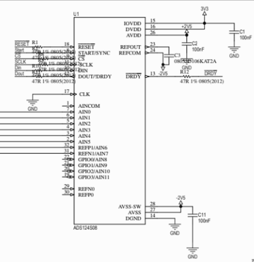
This is our actual HW connection:
These are the steps that I follow to measure the analogue values between AIN0 and AIN1:
- Read AD Status
- Write AD Registers
- Read AD Registers and check that the write/read data are the same
- Send digital signal to start
- I have a external interrupt with falling edge detection connected to DRDY signal
- Read data direct, sending 0 through SPI when the external interrupt is triggered. SPI works with a frequency of 4MHz.
Result:
I receive in the first byte the status as I expected, because I configured it so, but the rest three bytes are always 0.
I have tested with different configurations, but still does not work.
This is my actual Register configuration:
- Inpmux=0x01; (AIN0 as positive channel, AIN1 as negative channel)
- Pga=0x08; Pga enabled, Pga gain = 1
- Datarate= 0x1D; (Global chop disabled, internal clock selected, Continuous conversion mode, Low latency filter, 4000SPS.
- Ref = 0x3A; (Reference monitor disabled), Positive and negative reference buffer disabled, Internal reference selected, Internal reference is always on
- Idacmag=0x00; (Pga rail flag disabled, low side power switch open, idac magnitude off)
- Idacmux=0xDD; (Idac1 and Idac2 disconnected)
- Vbias=0x00; Vbias disconnected
- Sys=0x11; (System monitor disconnected, 8 samples, spi timeout disabled, crc disabled, status enable)
- Ofcal0,Ofcal1,Ofcal2,Fscal0,Fscal1,Fscal2=0;
- Gpiodat=0x00; (GPIOs configured as output, GPIOs low)
- GpioCon=0x00; (GPIOs configured as analog inputs.
I selected PGA enabled and Gain 1 because I saw in datasheet that for Single-ended input and bipolar power supply the Pga should be enabled, but I have also tested with PGA disabled.
I disable the reference buffers because I saw in datasheet that when the internal reference is selected for measurements, these must be disabled.
I have also tested with Sinc3 filter instead Low latency filter.
I have also tested enabling the Reference monitor and the PGA output rail flag to check if there is any fault, but the status that I receive does not change, it is always 0x80, without any fault.
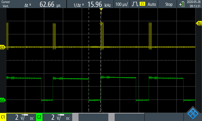
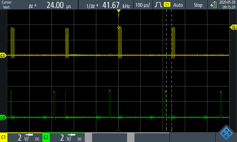
These are some pictures of DRDY, SCLK and DOUT signals:
- DRDY signal and SCLK
- SCLK and DOUT
- SCLK and DOUT with zoom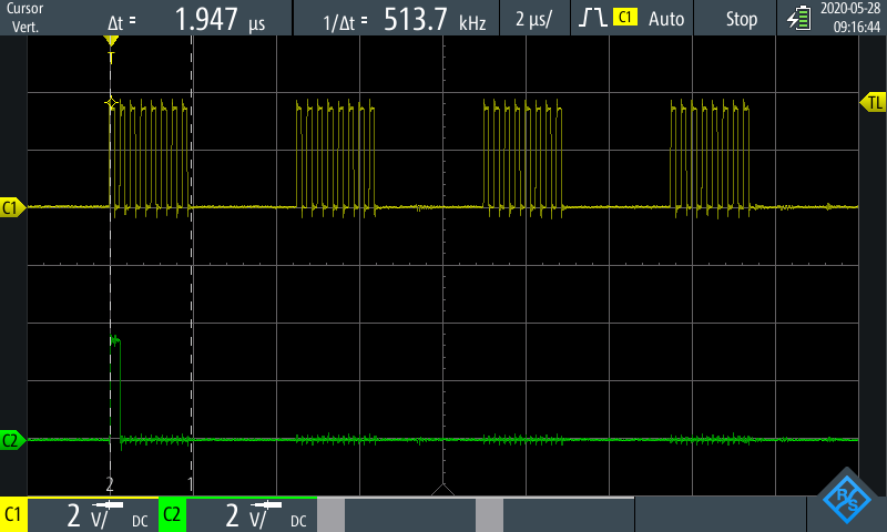
I have also check the status of the following signals during the measurement:
- RESET is always high
- START is always high
- CS is always low
Please could you tell me if the configuration is correct and if I do something wrong? Because I read always 0.
Thank you very much in advance.
Kind Regards
Jenifer Blanco

