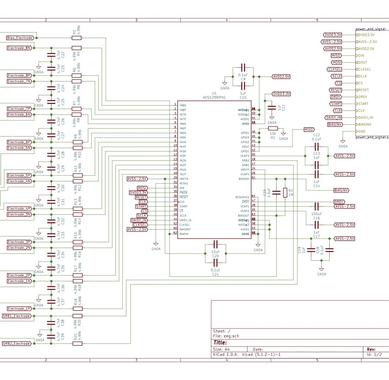
I recently made a board with ads1299 and bipolar supply.
Everything works fine until I started generating internal test signals.
Register 2: 0b11010011, CHnSET: 0b00000101
What I expected to see: 1 × –(VREFP – VREFN) / 2400 = 4.5/2400 = -0.0018
What I got instead: -0.0024017
When I set CAL_FREQ[1:0] to 00, the amplitude seems correct, but still skewed a bit more towards negative side.
Register 1 Setting: 0x96, Register 2 Setting 0xE8
Measurement of Vref = 4.5V
I checked ADC conversion with against this forum, https://e2e.ti.com/support/data-converters/f/73/p/772488/2856893#2856893, and it seems to work as expected.
Conversion Snippet: Channel1 | FFEE83 | -0.0024017
I attached schematic as well. I'm a newbie, so I really appreciate any help I can get :)


