This thread has been locked.

If you have a related question, please click the "Ask a related question" button in the top right corner. The newly created question will be automatically linked to this question.

ADS1292R: Huge noise in the original ECG signal acquired

Part Number: ADS1292R
Other Parts Discussed in Thread: TPS63030

Hi guys,

I'm using the ADS1292R. My custom board can get the ECG signal successfully, but the original data has a lot of noise.

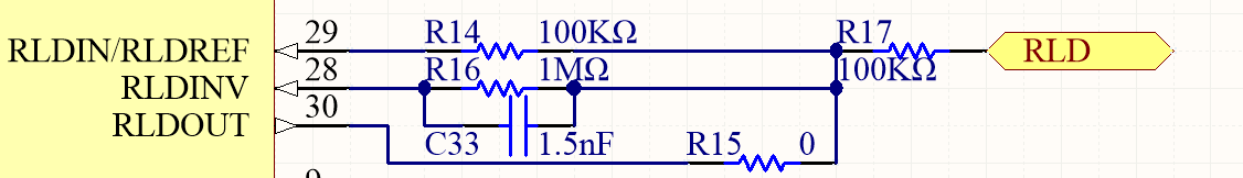
I try to separate the DGND and AGND and the GND of my power source, and connet the DGND to GND with a 0 ohm resistor(I did the same between AGND and GND). The purpose is to reduce the EMI on the analog signal. I also used the RLD to make the result better.

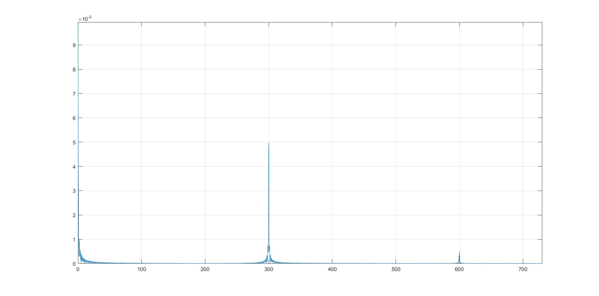
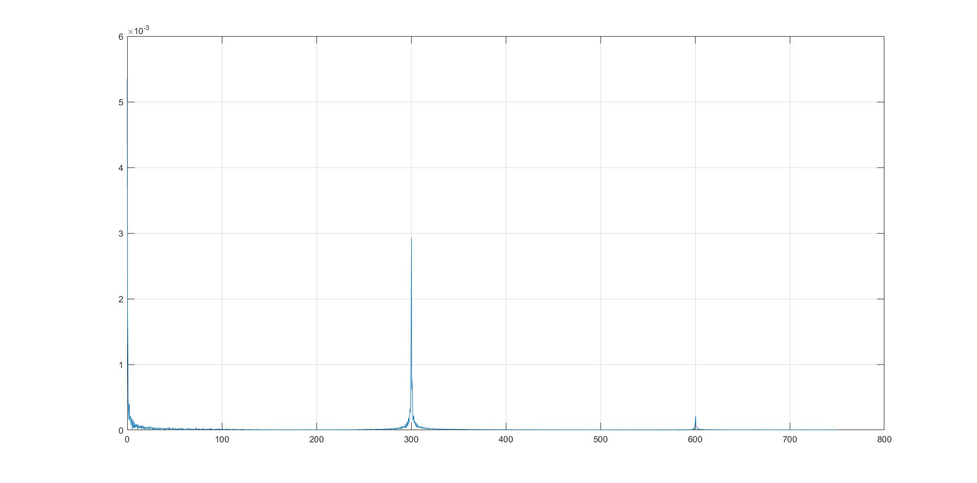
But the result is still bad. Here are somt of my result:

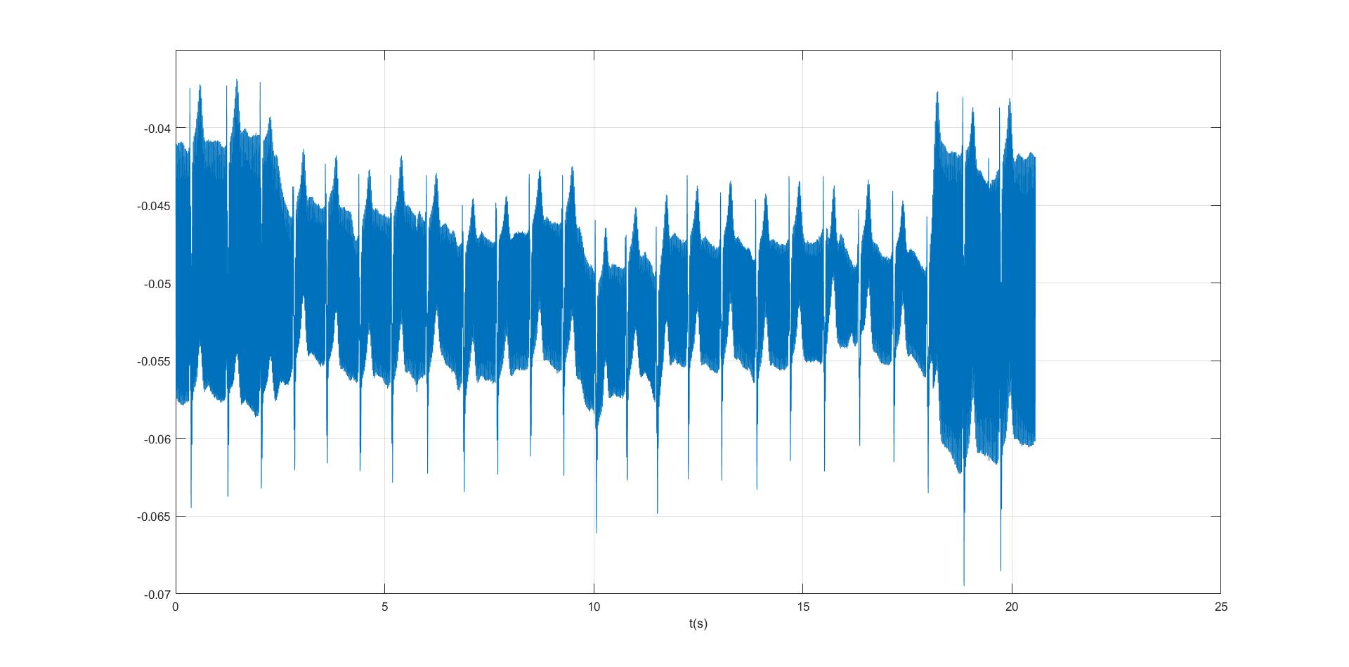
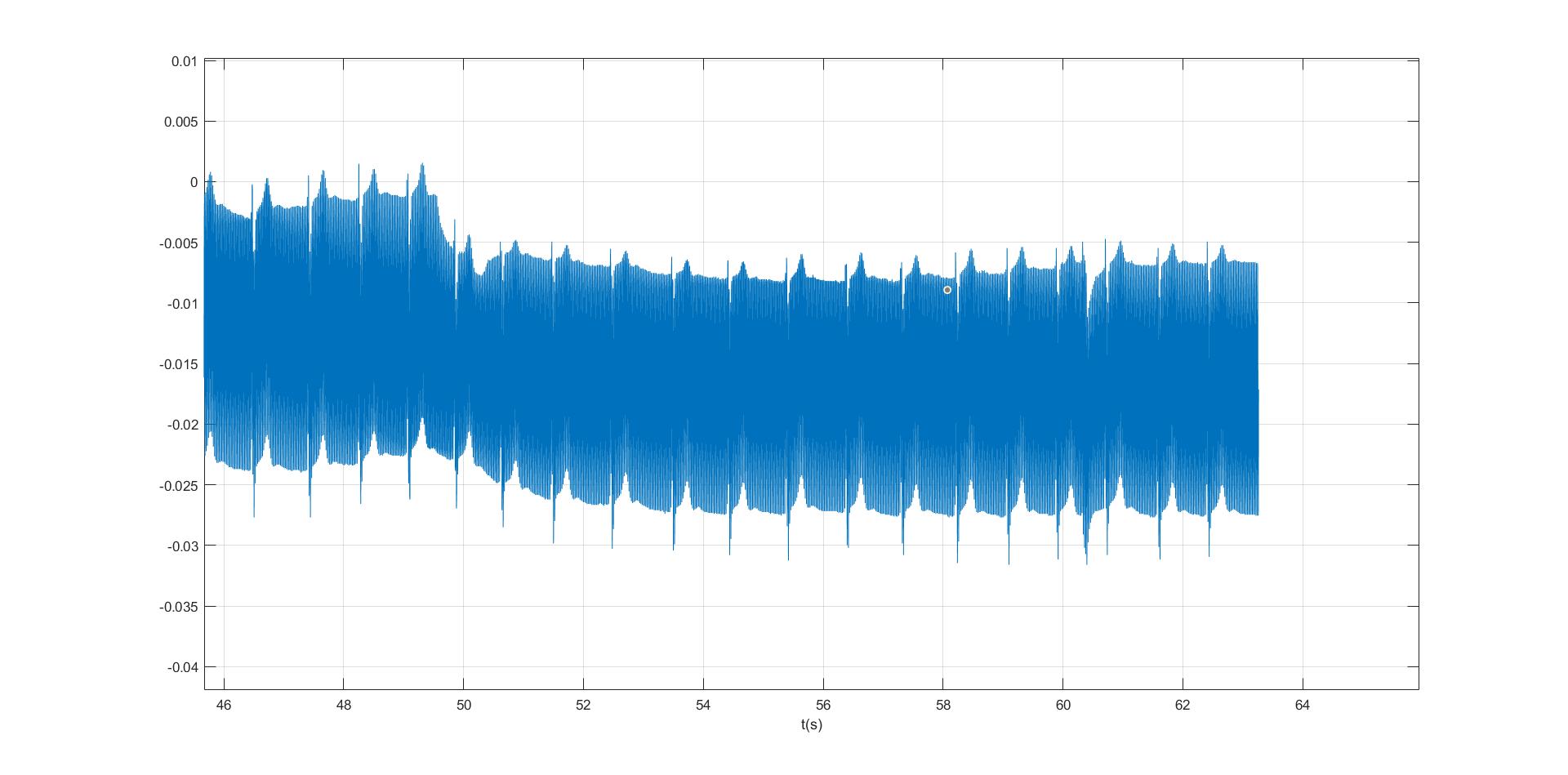
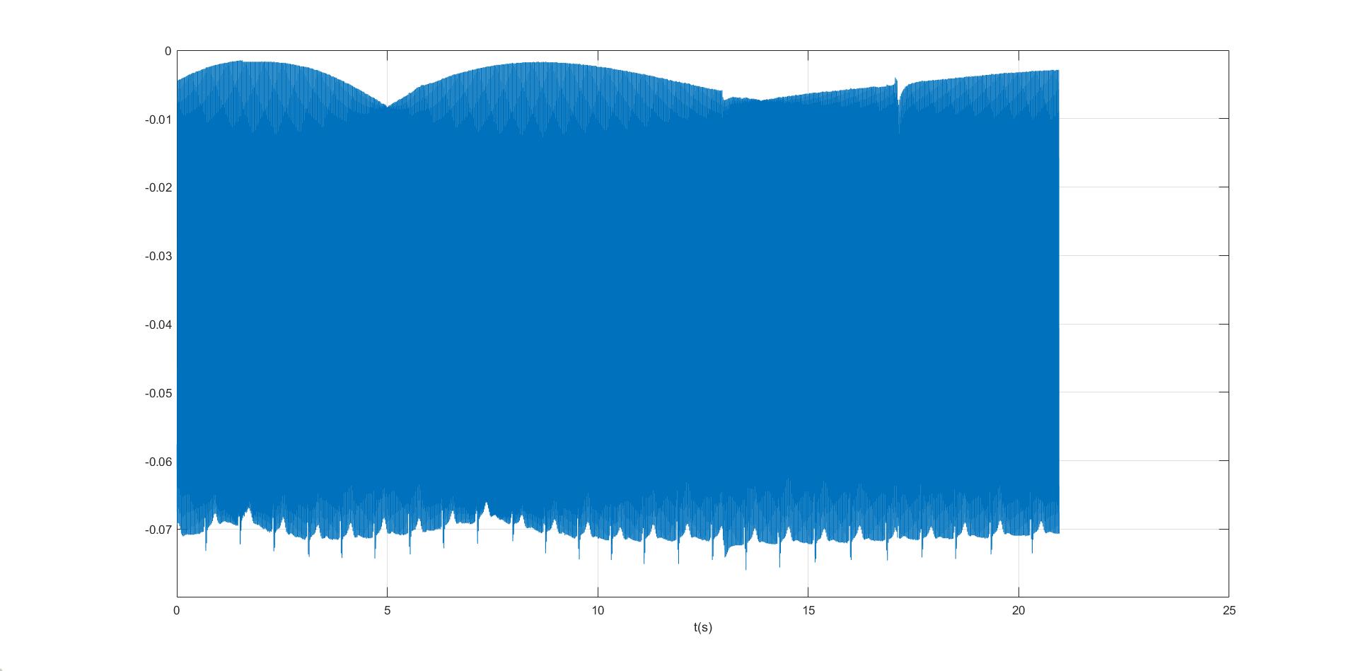
The ECG signal could be recognized obviously, but what the other noise is? Could it be the other kind of noise but the EMI?

I hope you guys could give me some suggestion to make improvement to my board.

Thanks a lot,

Yuhang

  • Hi Yuhang,

    Can you identify what frequency this noise is? 

    Are you using the RLD function of the device for this board? 

  • Hi Alex,

    I tried to use the RLD function. I wrote 0x2F to RLD_SENS register.

    I find the frequency of those noise is 300Hz and 600Hz, there are two peak in the figure of frequency:

    The low-pass RC filter has been applied on the two channels' input, the resistor is 51.1K ohm and the capasitor is 3000pf.

    So I thought I should change the value of the capasitor to 12 or 15 nf. Could it help to block the norse?

    If I set the value of resistor higher, could it help to make the result better?

    Thanks,

    Yuhang.

  • Hi Yuhang,

    Increasing the filter cutoff frequency in an effort to eliminate this noise may help. However, the RLD function of the device should also be capable of removing this noise from the measurement. But it will not be able to do so if the RLD loop cutoff frequency is too low.  What is the cutoff frequency of the RLD loop?

    Can you identify the source of the noise?  

  • Hi Alex,

    Because the noise contains 300Hz and 600Hz, and the cutoff frequency of the low-pass filter on the input side is about 1038Hz. Should I still increase the cutoff frequency?

    I didn't apply a filter on the RLD loop, I draw the RLD schematic like this:

    Do you mean that I should put a low-pass filter on the RLD?

    I could not tell what source the noise comes from. There are a BLE and a MSP430 on the board, but their DGND are separate from AGND. Further more, to the BLE, 300 and 600Hz is too low. So BLE cannot  be the source. Do you think the MSP430 could cause those noise?

    Thanks,

    Yuhang.

  • Hi Yuhang,

    R16 and C33 actually form a filter and the cutoff is 106Hz. Since this cutoff frequency is lower than the noise in the measurement, the RLD loop can not effectively bias the patient with the 300 or 600Hz inverse signal.

    I would first try increasing the cutoff frequency of your RLD loop (to at least 1kHz) to test how effective it is at cancelling the noise. The problem with decreasing the anti-aliasing filters cutoff frequency is that there will inherently be some mismatch in filter response due to passive tolerance. This mismatch will allow some of the noise to been seen in the measurement. If the cutoff frequency of the anti-aliasing filter is higher, than the noise that's present on both the positive and negative inputs are cancelled out at the PGA. VINP - VINN = measurement. 

    Are there any LDO's or regulators on the board? Perhaps they are switching at this frequency? How is the board being powered? 

  • Hi Alex,

    I used a TPS63030 to give 2.0V voltage to the DVDD of ADS1292R, and another TPS63030 makes the power of my board be 3.3V.

    I will try to make the cutoff frequency of the filter on the RLD loop. Do I need to change the value of R13? or only change the value of C33?

    Thanks,

    Yuhang.

  • Hi Yuhang,

    Just changing C33 should be fine.