This thread has been locked.

If you have a related question, please click the "Ask a related question" button in the top right corner. The newly created question will be automatically linked to this question.

DAC8771: CCOMP issue

Part Number: DAC8771

Hi,

Initially, the customer's DAC8771 had a large glitch when setting the "Buck-boost Config" register and VOUT Enable.
VOUT waveform
Configuration DAC Register(ADR:0x4) write 0x1613
Vout drop to -12V


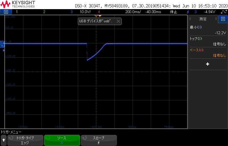
According to customer survey, CCOMP was connected to 2.2uF.
Removing 2.2uF improved the waveform at VOUT Enable.
VOUT:blue
VPOS:green
VNEG:red


Customer question
(1) What is the reason why VOUT dropped greatly when setting the register when the phase compensation capacitor  was connected on the CCOMP pin?
(2) It is a specification that glitch occurs at VOUT EN, but it is larger than D/S Output EN Glitch. Please tell me how to suppress this glitch.
Zoom up
VOUT Enable  glitch : 4V 

(3) It seems that the capacitor at the output stage is not mounted on the evaluation board.
      (slau727, P14 fig.12  : C19 )
      We would like to keep this capacitor, but please let TI know if you have removed this capacitor.
     

From the D/S description, I understand that CCOMP is for phase compensation of large capacitive load drives.
It is presumed that the AC characteristics deteriorated because a very large capacitor was connected to CCOMP,
even though there was no capacitive load. Additional commentary from TI deepens customer understanding.
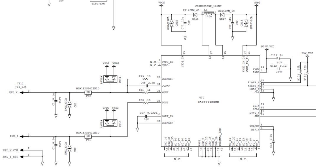
Our customer schematic is also attached.
Best regards,
Hiroshi
  • A little fix

    (3) It seems that the output stage capacitor is not mounted on the evaluation board.
    (Slau727, P14 fig.12:C19)
     we want to keep this capacitor, why did TI remove it? Please let me know if there is a reason.
  • Hello,

    I'll make some general comments before responding to your specific questions. The DAC8771 VOUT DAC is cable of driving capacitive loads up to 1uF. For capcitive loads greater than 20nF, the compensation capacitor must be placed between CCOMP and VOUT. The value of the compensation capacitor is 150pF. Ccomp is required for the larger capacitive loads to ensure DAC stability and it works by reducing the bandwidth of the VOUT DAC buffer. 

    1. The customer uses 2.2uF ccomp in their design. This value is significantly larger than the 150pF requirement and will likely reduce the VOUT bandwidth such that the system response is extremely slow to step changes. This is likely the reason why the glitch is large after enabling the DAC. 

    2. Please ask customer to replace ccomp with 150pF and retest. Again, this is necessary when driving cap loads between 20nF and 1uF

    3. It is okay to have an output capacitor on VOUT (C19). The output capacitor and ccomp are not installed by default for the EVM board just to give customers flexibility to test different output load configurations. 

    Regards

    Reza

  • Reza-san,
    Thank you.
    For Q2, I ask the customer to adjust the output circuit.
    Regards,
    Hiroshi