This thread has been locked.

If you have a related question, please click the "Ask a related question" button in the top right corner. The newly created question will be automatically linked to this question.

ADS1252: At what timing does the analog value of ADS1252 become the conversion data?

Part Number: ADS1252

For the convenience of the system, we are thinking of acquiring data in 1tDRDY cycle.
(Of course, 5 cycles after start-up are discarded.)
We hope the evidence that there is no problem even if only the 6th cycle data is applied as valid data.
Although there is a description of the conversion cycle in the data sheet, there is no description of what timing the analog value becomes the conversion data, so I asked such a question.

  • Hi User,

    I am sorry, I do not clearly understand the question you are asking. Can you please explain in more detail what you want help with?

    -Bryan

  • I would like to be sure that my understanding is correct before I provide additional explanation.
    I checked the ADC1252 data sheet again.
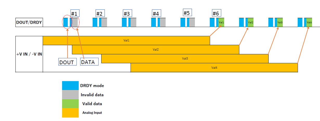
    From the description of the delta-sigma modulator, the conversion results (DOUT/DRDY) and the analog input values (+V IN /-V IN) is roughly as shown in the diagram, is it correct?

  • I was unable to attach a diagram.
    I'll write again.

  • Sorry for repeating myself.
    I'll write again.

    Is the diagram attached?

  • Sorry for the confusing post.
    You can ignore the previous post.
    What is the sample hold timing for the ADS1252?

  • Hi user,

    As you can see from Figure 12 from the ADS1252 (shown below), the ADC has two modes: DRDY mode and DOUT mode. You should monitor DRDY to know when data is ready to be clocked out by the ADC.

    The device will take time t4 to sample and convert the analog input. When the data is ready, DRDY will go low for time t2 and then go high for time t3. Both t2 and t3 are 6*CLK (typ) according to Table 2.

    At this point, the device changes to DOUT mode, where you must issue 24 SCLKs to get the conversion result. This must be completed in the time given by DOUT mode in Table 2 (348*CLK), or the data can become corrupted as the next sample period begins. In other words, the ADS1252 does not have an integrated buffer to hold the data for longer than 1x conversion cycle, so ensure that the timing in table 2 is met.

    Also note that on startup, data is not valid until you have seen 6x DRDY pulses, as described in the datasheet. This is to give the digital filter time to "fill up" since it is a sinc5 filter.

    I hope this helps you get the ADS1252 working for your application.

    -Bryan

  • Hi Bryan

    Thanks for the reply.
    I had a general understanding of the timing in this area.
    What I wanted to know was what timing to sample and hold.
    From the description of the digital filters in the datasheet,
    I was able to see that it was for 5 conversions (or 6 if it was an asynchronous analog input) I decided to hold from the front.

    Takayuki

  • Hi user,

    You are correct, the ADS1252 has a sinc5 filter so you need to wait 5 conversion periods for the filter to fill up. But, if the signal is not settled when a conversion starts, you might need to wait an additional cycle - hence the need to wait 6 conversion cycles.

    Note that after waiting the 6 conversion cycles, you should be able to get data out at a frequency of 1/data rate for subsequent conversions assuming there are no step changes to the input. If there is a step change, you would be required to wait the 5 or 6 conversions to get settled data.

    It sounds like are you aware of this functionality, so let me know if you need anything else.

    -Bryan