This thread has been locked.

If you have a related question, please click the "Ask a related question" button in the top right corner. The newly created question will be automatically linked to this question.

ADC12DJ5200RF: system start-up procedure

Part Number: ADC12DJ5200RF
Other Parts Discussed in Thread: LMH6401

Hi

I use an ADC12DJ5200RF on a board that I designed myself.

At present, I am suffering from the problem that the result of AD conversion is sometimes disturbed.
When I read out the ADC registers when the problem occurred, the value of [7:0] at address 0x2B2 was different from the normal operation.
So I would like to ask if there is anything wrong with the current initial startup procedure.

・Configuring Clocks and Periodic SYSREFs for FPGAs and ADCs
・Setting registers in the ADC and performing SYSREF calibration
・Configuring JESD204 IP in FPGA
・Perform foreground calibration of the ADC
・SYSREF Delay Adjustment in FPGA

The ADC and FPGA are connected in subclass 1 of JESD204B, and the SYNC signal indicates that the connection is valid.
However, sometimes the result of AD conversion becomes so noisy that the waveform cannot be seen.
Is there any way out of this situation?

I follow the procedure for setting the ADC registers in Section 9.3.

  • Hi Hanawa-san,

    Could you please provide a good and bad signal waveform if possible? FFT would be best.

    If you can provide the schematics as well of your board that would help too.

    Thank you,

    Rob

  • Hi,

    Circuits are difficult to provide because they are hierarchical and complex.
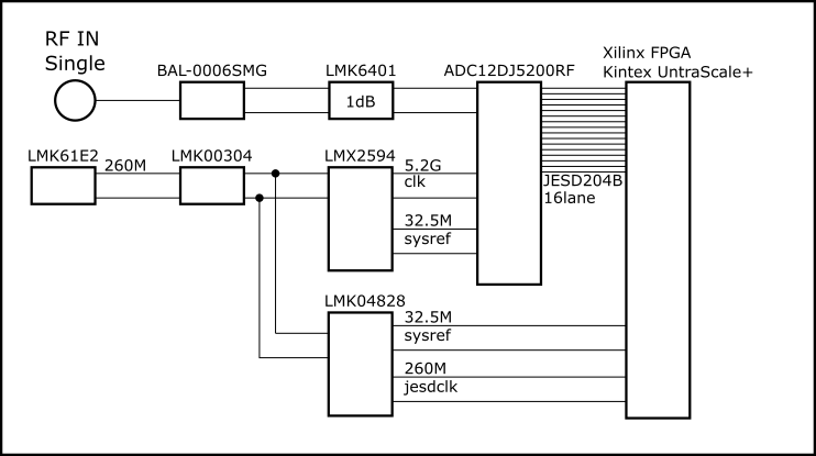
    However, we can provide a block diagram.
    I have attached the FFT results for error and normal times.
    This is the FFT result when Reader1 is in normal operation and when Reader2 is in error. The original waveform data was not available.

      FFTdat.xlsx

  • Hi,

    I should check the LMH6401 interface with the ADC that seems to be the problem. The FFT seems to have a common mode mis-match between the LMH VGA output and ADC input. This can be checked using a DMM, they should be the same on both channels. Is there a reason you are DC coupled if the inputs of the LMH is AC coupled?

    Regards,

    Rob

  • Hi,

    It may not be good that the input to the ADC is DC coupled.
    Thank you very much for your advice.

    However, when the output of the amplifier is input to the ADC through the DC coupling, does the Fine Delay value change and the result of the ADC may or may not be stable?
    Does the Fine Delay value have much to do with the output of the ADC?

  • Hi,

    The fine delay or tadj would help with the delay in sample clock timing, it could be possible to effect the output performance if the fine delay skews the setup and hold times when capturing the ADC data.

    Regards,

    Rob