This thread has been locked.

If you have a related question, please click the "Ask a related question" button in the top right corner. The newly created question will be automatically linked to this question.

ADS52J90EVM: How to modify the board to accept DC signal?

Part Number: ADS52J90EVM

My input signal comes from optical sensor. The application is to measure light intensity. Signal bandwidth is about 0-1MHz. All the channels on the EVM board are AC coupled through Transformer or capacitor. How do I make changes to test the DC coupling? 

Thank you

  • Hi,

    Thanks for using ADS52J90EVM.

    We will forward your question to our group engineer.

    Thank you!

    Best regards,

    Chen

  • Hi,

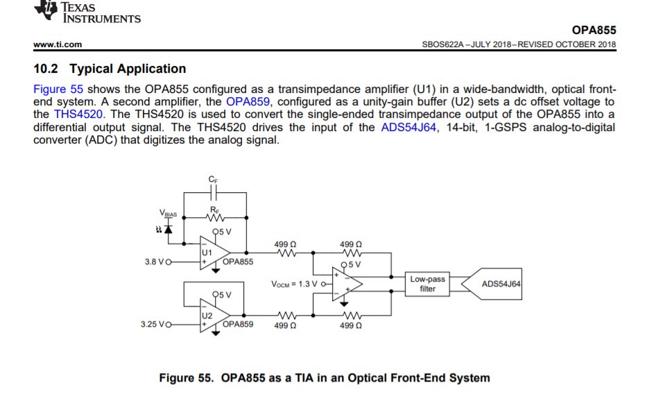
    Most likely you need to get an OPA EVM board and do something like this.


  • Hi, Chen,

    Really appreciate your feedback. However, your reply didn't seem to address my question. I am asking about modifying the signal path on the ADS52J90EVM board to measure DC signal so square wave is measured as a square wave. With current AC coupling design, the square wave is heavily warped. Some of your evaluation boards such as ADC34xxEVM have DC coupling options by soldering adjustment.  Is there a way to do it on ADS52J90EVM?  or I would have to make my own board following ADC34xxEVM DC coupling design? 

    Thank you.

    Heng