This thread has been locked.

If you have a related question, please click the "Ask a related question" button in the top right corner. The newly created question will be automatically linked to this question.

TSW3100 with DAC 5682

Other Parts Discussed in Thread: DAC5682Z, CDCM7005

Hi,


I'm trying to use the TSW3100 setup along with the DAC5682z EVM for a CCD waveform application.


I'm unable to get D18 (LVDS PLL LOCK) on even though I've supplied clock at J6.Is there a mistake with what I'm doing.


I can be reached at akrishnan@ti.com


Thanks

  • Hello

    Are you following DAC5682z EVM user guide recommendations on clock and input voltage levels and have you configured the CDC correctly on the DAC EVM? Send me your operating conditions and I can send you the configuration settings for DAC and CDC.

    Regards

  • Hi Hamza


    Thank you for the reply.


    I managed to get the configurations right and can transfer data from the TSW3100 to the DAC5862Z.


    However, post conversion, I'm unable to get more than a few mV of output on the scope despite giving all 1's as the input.(I expect a voltage of around 1.2V).

    I'm guessing that there is a problem with the way I'm generating my pattern. I'm using the MATLAB GUI that comes along with the board.


    Could you help me with how I generate the pattern to get for eg a sine wave?

    Best Regards


  • Aswath,

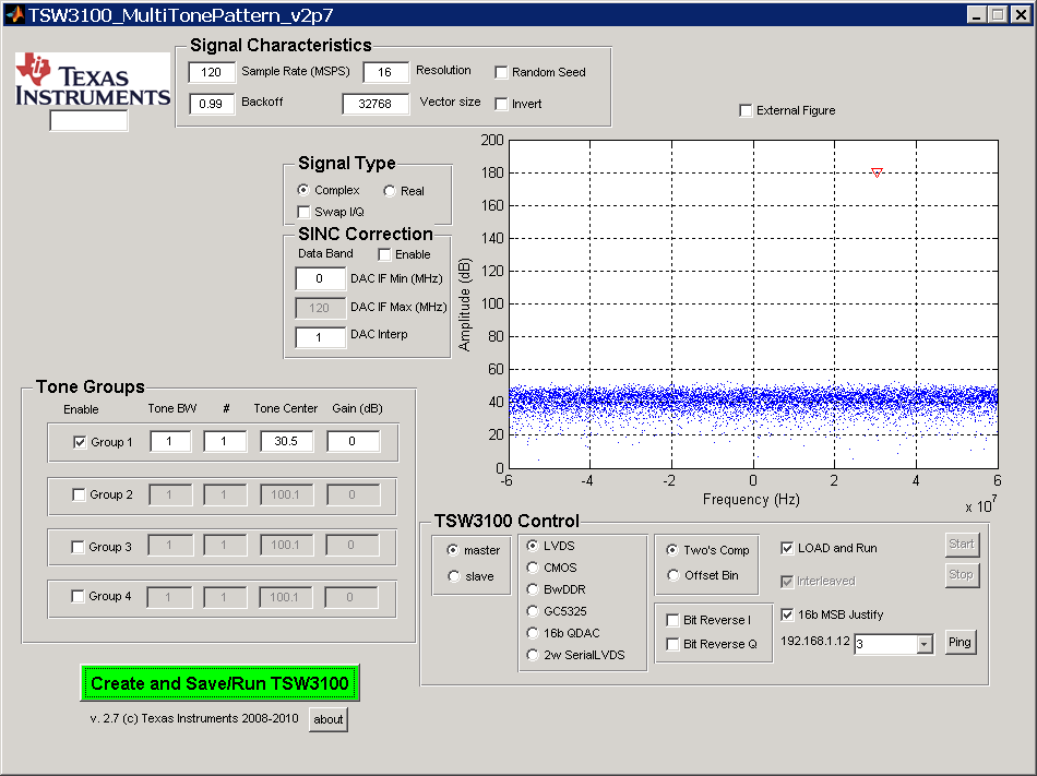
    The DAC output goes through transformer to the SMA connector so low frequency or near DC signals are attenuated. Try some frequency beyond the cutoff of transformer. e.g. the attached snapshot illustrates generation of a 30 MHz tone at 120 MSPS data rate. TSW3100 and DAC5682z EVM user guides illustrate with figures how to generate data for the EVM.

    Regards

  • Hi Hamza,

    Thank you for you reply. Yes I did realize that low frequency signals are not really reconstructed properly. However, a problem I face is that even high frequency signals of the order of 30 Mhz and more are not reconstructed correctly.

    For example the above settings which you suggested for generating 30MHz sine wave returns a sine wave but of frequency of around 13 MHz, as attached in the figure below. Initially I thought my scope wasnt functioning well but later after checking, I'm reasonably sure that my scopes here at TI labs are good.

    An image of my DAC configuration is also shown below.

    I'd like to add that my VCXO_P is at 80 MHz, another value that I think could be problematic.

    Is there a conversion factor that I'm missing?

    Kindly advise

    Best regards


  • Aswath

    Your configuration for EVMs for getting the desired output is incorrect.

    First, Your DAC clock is 80 MHz and you have set the DAC for 2x interpolation, that means your data rate into the DAC is samnpled at 80/2 = 40 MHz (fDATA = fDAC/INTERPOLATION). Therefore, the TSW3100 GUI should have sampleing frequency 40 MHz instead of 120 M. Then 30 MHz IF is too high for 40 MSPS so lower it to 5 MHz.

    Then the Y2 divider in the CDC settings need to be set to 8.

    Since your fDATA is slow (less than 125 M), as per the datasheet, you have to disable the DLL.

    I strongly recommend you to go through user guide of DAC5682z EVM and construct the example setup mentioned there to learn all these steps.

    I can also help you by sending the configuration settings files for DAC5692z EVM if you let me know your operating conditions.

    Regards

  • Hi Hamza

    Thanks for the reply.

    I understand I was looking at the wrong guide (TSW3100 with DAC5682z) instead of the TSW3082 with DAC 5682z where register configurations are explained.

    I'm now able to generate the correct sine waves.


    Just to clarify, the sampling rate of the DAC is [VCXO_EXT_P/Interpolation] and the TSW3100 clock used for data transfer is given by  [CDCM7005 output frequency/ Y2], right?


    I'm currently trying to generate a ccd input waveform as shown below.

    I'll post again when I run into some trouble.


    Thank you once again for the assistance. I really appreciate it.

    Best Regards

  • Aswath

    DAC5682z expects two clock signals: DATACLK and DACCLK

    DACCLK is the sampling frequency of the DAC and if you are not using any PLL, is equal to whatever clock you supply at EXT_VCXO_P (J6) input of DAC5682z EVM.

    if you are using DAC5682z EVM, I would like you to refer to this user guide:

    http://focus.ti.com/lit/ug/slau236a/slau236a.pdf

    DATACLK clocks the digital data *into* the DAC and is equal to DACCLK/INTERPOLATION

    The Y2 divider clock is the clock to the FPGA of TSW3100, which in turns drives data into the DAC EVM and generates DATACLK. It is equal to ((DACCLK*2)/INT)/8.

    The user guide referred to includes all these details

    Regards

  • Hi Hamza,

    Thank you for clarifying.

    Another issue that has cropped up with my DAC setup is a 200mV 250kHz "ramp like" noise that shows up with all input values that I provide.

    This noise occurs with all DC levels except levels close to the mid level of full scale.

    Further, the frequency and the amplitude of the oscillation changes as I modify the 3.3V input to the board. The oscillation dies when I average it over time. I'm trying to identify where this oscillation comes from. The oscillation completely dies when I provide about 2.2V instead of 3.3V

    My setup uses a 200MHz clock. I haven't powered the 5V going to the RF modulator(U8) on the DAC, and the noise still continues to be there even if I kill power to the  quartz crystal oscillator(U3) on the board.

    All my power supplies are Low dropout so I don't really expect them to switch. I also haven't used EXT_REF_CLK or a clock input to the FPGA.

    My guess is that one of the VCO's in the PLL's either in the CDCM7005 or the FPGA is the source. Alternatively, the internal reference bandgap could be the reason.

    Is there a way I can identify and get rid of these unwanted oscillations?


    Thanks and Best Regards


  • An image of the above noise is shown below.


    Best Regards

  • Aswath

    I do not fully comprehend how do you intend to use the dac evm. If you could send me your operating conditions; fDAC, Interpolation, IF/BW requirement, single/dual dac mode etc, I can send you configuration settings for DAC EVM (for DAC5682z as well as CDC)

    Regards