This thread has been locked.

If you have a related question, please click the "Ask a related question" button in the top right corner. The newly created question will be automatically linked to this question.

ADS122U04: Is there an easy way to convert 24bit A/D converted output of ADS122U04 into Temperature into Degree Centegrade?

Part Number: ADS122U04

Hello Bob,

What is the easiest way to convert 24bit A/D converted output of ADS122U04 into Temperature into Degree Centegrade?

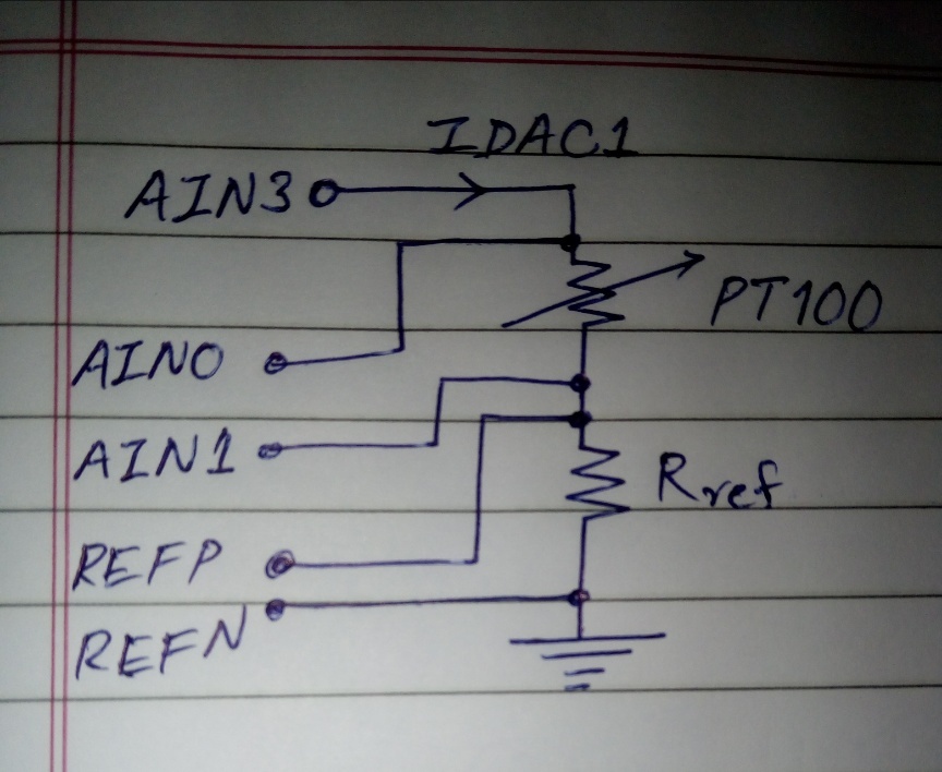
I have exactly followed the datasheet of ADS122U04 and assembled it's circuit on a general purpose PCB.
I have studied the design formulae mentioned in the datasheet and accordingly calculated the Rref value.

So, in my circuit, the Rref is 3K3, Dvdd=Avdd= 3v3dc, IDAC2 (output through AIN3 i.e. pin no 6) is 500uA.
The sensor used is RTD PT100.
The circuit is functioning great and I am getting a A/D converted 3-bytes output count as: D4CA62  
at ambient temperature of around 30 degree centigrade. At this point the PT100 resistance is 111.2 Ohms
and differential voltage between AIN0 and AIN1 is 106 milliVolts.
Please let me know what is the easiest way of converting this 3-bytes output count which is D4CA62 into Temperature value in Degree Centigrade.

The formulae given in datasheet are for the internal temperature sensor (14 bit output) of ADS122U04 but none for the 24bit output. Kindly help.

Regards,
Milind Risbud.

  • Hi Milind,

    I would highly recommend reading A Basic Guide to RTD Measurements.  There is a lot of good information in the guide.  As the measurement is ratiometric you can use the value of the reference resistor to determine the resistance of the RTD.  The output code relates to the RTD resistance relative to the reference resistance.  If you look at the ADS122U04 datasheet and equation 28 on page 58 you can see the relationship.  You can rearrange the equation and solve for the RTD resistance (RRTD = Code*RREF/(Gain*2^23), and then use lookup tables or Callendar-Van Dusen equation to solve for the temperature.

    Now I'm assuming that you are using either a 2-wire of 4-wire RTD based on the single IDAC used.  As to the return value of D4CA62, this is actually a negative value as the output code is binary 2's complement and it is a very large number. Make sure that you are reading the data correctly.  The output code is not MSB first but instead LSB first.  Usually your micro peripheral will change the bit order of each byte, but not the order of the bytes, so the code returned may actually be 62CAD4, which would be a large positive number.  If you are using gain, such as 16, then this number is more reasonable but still higher than I would expect.

    Best regards,

    Bob B

  • Hello Bob,

    Extremely thankful to you for replying to my query in a easy-to-understand way-
    and almost zero turn-around time.
    Now I am clear about how to derive the temperature value from the A/D code.
    Now, first, I will reply to questions asked by you above and then ask one another query (Confusion about IDAC).
    To answer your questions:- 

    Yes, I am using 2-Wire RTD configuration with a single IDAC.
    I have not populated the filter circuits (across RTD and Rref) yet, as I am still working on the core part.
    Yes, I also am doubtful whether the return value of D4CA62 is a negative value, but the ambient temp.
    at my desk is (30 DegC) [Indian Monsoon season and AC turned OFF :)]. 
    The reason why I think it may not be 62CAD4 is because:
    a) I have configured the UART of my uC as LSB first, so as to match the ADC code output format.
    b) In my test setup, when I increase the temperature of PT100 (using Hot air Blower)- 
        the MSByte 'D4' remains most stable, 'CA' varies slightly more and LSByte '62' continuously varies.
    With rise in temperature there is a drop in this count (and vice versa) i.e.  MSByte changes as D3....D2.....D1. .....and so on. 
    In the image that I have inserted (with Rref = 6.8Kohm), the count is even bigger, and the change can be seen as I described.
    Regarding Gain, yes you guessed it right, I have set the Gain as 16.  

    Now, Regarding the problem that I am facing with IDAC:
    As you know I am using Ratiometric measurement configuration.
    I am observing that irrespective of the IDAC value that I select in Configuration Register 2,
    the IDAC is getting decided by DVDD (3.3vdc) and Rref (1.65K or 3.3K or 6.8K) that I connect across REFP and REFN.
    With Rref=6.8K, the IDAC is 0.483mA (approx 0.5mA)
    With Rref=3.3K, the IDAC is 0.96mA (approx 1mA)
    With Rref=1.65K,the IDAC is 1.909mA (approx 2mA) and
    Thus, I observe different values of IDAC while the one selected by me in Config Reg2 is constant i.e. 500uA.
    So, the selection of IDAC value in Config Reg2 seems to have no effect on the actual value of IDAC.
    Can you please suggest why this may be happening? Kindly see the inserted image2 below:


    Thank you once again,
    Best Regards,
    Milind Risbud.


  • Hi Milind,

    I see that you created a new post so I will answer on that thread:

    https://e2e.ti.com/support/data-converters/f/73/t/917852

    Best regards,

    Bob B