


Hello, all.
I am implementing 8-Ch EMG system based on ADS1299 (Arduino UNO is used as MCU).
I have 2 problems:
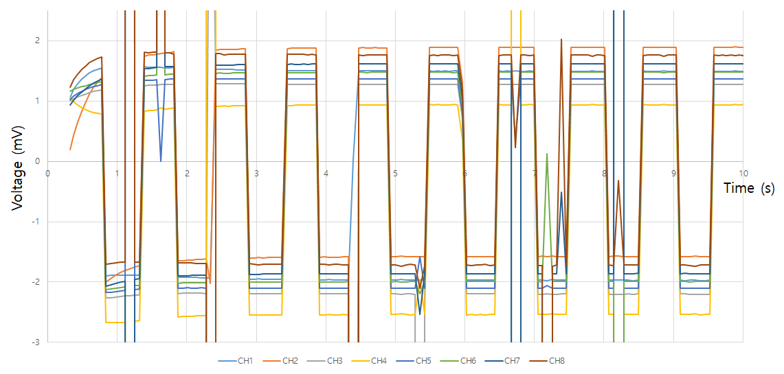
1. Signal outlier is showing on every setting even internal test signal.
When I check the internal test signal, registers setting:
CONFIG1 = 0x96
CONFIG2 = 0xD0
CONFIG3 = 0xE0
CHnSET (All channals) = 0x05 (not floating, connected to AVDD)
And checked values (VCAP checked with closest capaciter):
VCAP1 = 1.19V
VCAP2 = 2.5V
VCAP3 = 6.87V
VCAP4 = 2.27V
VREF = 4.48V
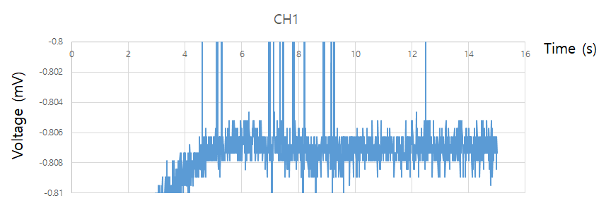
2. I didn't have any output when electrodes are attached to skin(muscle).
When I check electrode signals, I focused on only Ch-1.
My setting:
CONFIG1 = 0x96
CONFIG2 = 0xC0
CONFIG3 = 0xE0
CH1SET = 0x30 (I checked every gain)
CHnSET(Ch-2~8) = 0x81 (not floating, connected to AVDD)
And checked values (VCAP checked with closest capaciter):
VCAP1 = 1.19V
VCAP2 = 2.5V
VCAP3 = 6.87V
VCAP4 = 2.27V
VREF = 4.48V
My signal was showed that:
I have ADS1299EEGFE-PDK. Using this domo kit and in the same electrodes and behavior, signal was showed that:
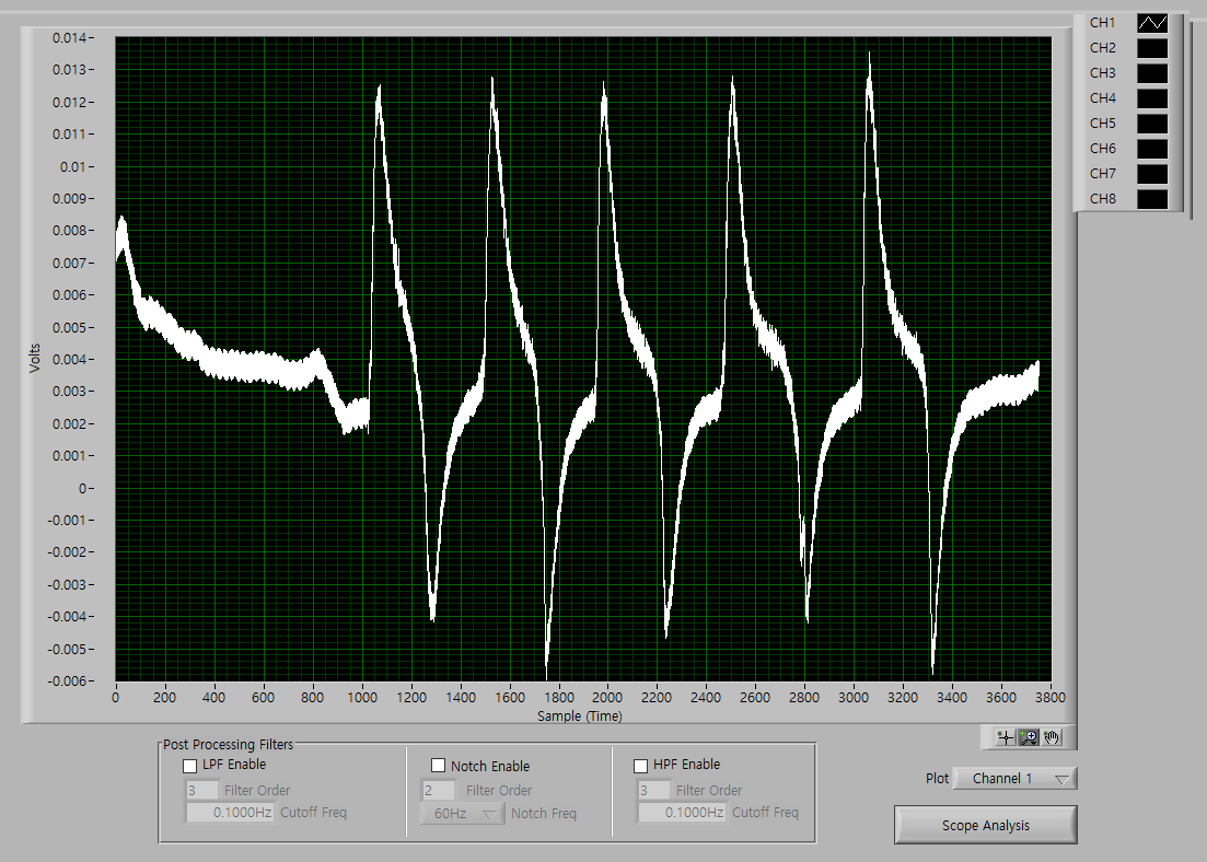
I don't know why didn't make any signal without noise. I checked internal test signal, VCAP1~4, VREF, and Device ID(it is 111110, same whith ADS1299EEGFE-PDK).
How can I fix these problems?
Thank you.
Best regards,
Woochang Jung
