This thread has been locked.

If you have a related question, please click the "Ask a related question" button in the top right corner. The newly created question will be automatically linked to this question.

ADS8681: Device disrupting SPI on Arduino Due

Part Number: ADS8681
Other Parts Discussed in Thread: , DAC8830

I am trying to work with the ADS8681 through the SPI interface of an Arduino Due, so that I can obtain 16-bit A/D resolution on the Due.  However, I have run into big problems.  I don't get accurate readings from the ADS8681, and furthermore, it disrupts the function of other SPI devices.

I followed the datasheet as accurately as I could (Figs. 53, 71), and confirmed my understanding using the ADS8681EVM-PDK circuit diagram (Fig. 21).  The SPI interface on the Due uses 3.3V logic, and I'm using the 5V power from the Due as AVDD and DVDD for the ADS8681.  I left pins 10 (RVS) and 11 (SDO-1) floating, and 9 (RST) tied high.  There are 50-Ohm resistors on the SPI lines.

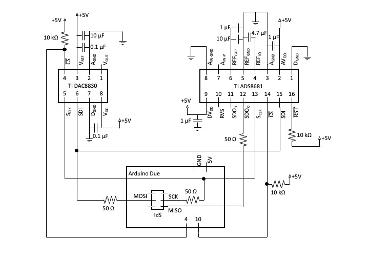
I monitored the SPI outputs from the Due with an oscilloscope, and when the ADS8681 is disconnected, all act as expected.  That is, when chip select (CS) goes low, MOSI also goes low (which I understand to be the read command), and SCK has sixteen 3.3V pulses.  However, when I connect the ADS8681, the voltage measured at the SCLK pin has a 100 mV offset, and each peak pulse is <1 V.  On Due side of the 50-Ohm resistor, SCK has an offset (500 mV), which goes to 0 when CS goes low, and the clock peaks remain 3.3V.  This makes me think the S_CLK pin on the ADS8681 is a low resistance path to ground, which is strange.  This does not appear to be a power supply problem: ground and 5V remain stable.  Also, SDI (pin 15) on the ADS8681 appears to be always floating, which I guess is "tristate".

I'm also using the TI DAC8830 to obtain 16-bit D/A resolution.  That device works fine with the Due when only it is connected to the SPI.  I can specify what output I want, and it does it.  When the ADS8681 is connected, the DAC8830 stops working, likely because the SPI outputs fall below TTL.

I would be grateful for help figuring out what is wrong.  Right now my theories are maybe that the chip is fried, or the breakout board I soldered it to is adding some fatal stray capacitance or something.  I tried a second chip, soldered by better hands than mine, but it has the same problem.  Thanks in advance,

-Matthew

  • Hi Matthew,

    You are making wrong connections to the ADS8681 ADC, see your schematic, the pin definitions and connections from pin 9 to pin 16 are totally wrong. For instance, pin 10 is SDI not pin 15 and pin 15 actually is RVS output, pin 13 is SDO-0 not pin 12 and pin 12 actually should be SCLK input. Please see correct pin definitions and connections below:

    Best regards,

    Dale

  • How stupid of me!  How many times I checked and rechecked!  Or maybe I shouldn't admit that.  Thanks for catching that.

  • Hi Matthew,

    No worries, let me know if you need any further support on this ADS8681 ADC.

    Thanks&regards,

    Dale

  • That did fix my problem, and I can now read from the device.  But now I have a new problem.  Since you offered further support, can you help with the programming?  I want to set the RANGE_SEL_REG Register, to set bits 0-3 to 1001b (i.e. range 0..10.24V).  As I understand it, this means doing a half-word write command, and in a dataframe, I am writing:

    [Bring CS low]

    write <11010_00_0><00010100> <00000000><00001001>

    (i.e. 0xD014 0x0009)

    [Bring CS high]

    However, the range is not changing from -12...+12.  What am I doing wrong?  Do I have MSB and LSB reversed?  Do I need to send another (dummy?) 32-bit frame to get this command to take effect?  Do I need to write to additional bits of the register?  (I did try adding a second write command to 0xD016, but that had no effect.)  Or should I be using the other variants of the half-word write commands that only change one byte at a time?  I would be grateful for your help.

    -Matthew

  • Hi Matthew,

     Your command is correct. When any of these commands are provided in a particular data frame F, that command will get executed at the rising edge of the CONVST/CS signal. How did you verify whether the input range of the device has changed or not? Are you converting a same analog DC input to check the output code or read back the register content in next frame? Can you please provide the timing for two frames including Convst/CS, SCLK, SDO and SDI?

    Regards,

    Dale

  • Yessss!  I think you suspected the commands were being sent incorrectly.  Indeed they were.  I am using the Arduino Due, and the SPI library is incompletely documented.  At the end of the first SPI.transfer16 command, it tried to set the CS line back high, which interrupted the complete 32-bit communication, and I guess the ADS8681 treated the interrupted command as a NOP.  The transfer16 command can take an optional argument that leaves the CS line alone.  I added that, and presto!  Now the gain is correct.  Thanks so much for your help and patience!  Resolved!

    -Matthew

  • Hi Matthew,

    Thanks for update.

    Best regards,

    Dale