This thread has been locked.

If you have a related question, please click the "Ask a related question" button in the top right corner. The newly created question will be automatically linked to this question.

ADS1115-Q1: Read the output value is 0

Part Number: ADS1115-Q1
Other Parts Discussed in Thread: ADS1115, OPA2187

Hi Team,

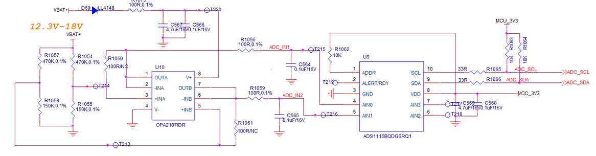
My customer now use ADS1115-Q1 and read the output value is 0.When reading the voltage, they  only use three functions:

  •          Ads1115_Config();
  •          Ads1115_PointRegister();
  •          VOL=Ads1115_ReadData()

Could you please give some advice?

/************************************************************
FileName:       bsp_iic.h
Author:         liamtsen  
Date:           2019/03/07
Description:    IIC����
***********************************************************/
#include "global.h"

//IO��������
#define ADC_SDA_IN()   SystemIoModeSetIn(GPIOB,RCC_AHB1Periph_GPIOB,GPIO_Pin_11)
#define ADC_SDA_OUT()  SystemIoModeSetOut(GPIOB,RCC_AHB1Periph_GPIOB,GPIO_Pin_11)
#define ADC_SCL_OUT()  SystemIoModeSetOut(GPIOB,RCC_AHB1Periph_GPIOB,GPIO_Pin_10)
//IO��������	 
#define ADC_SCL_H    GPIO_SetBits(GPIOB, GPIO_Pin_10)   //SCL
#define ADC_SCL_L    GPIO_ResetBits(GPIOB, GPIO_Pin_10)   //SCL

#define ADC_SDA_H    GPIO_SetBits(GPIOB, GPIO_Pin_11)   //SDA
#define ADC_SDA_L    GPIO_ResetBits(GPIOB, GPIO_Pin_11)   //SDA


#define ADC_READ_SDA   GPIO_ReadInputDataBit(GPIOB, GPIO_Pin_11)


//ʱ���õ�48M��һ����������1/48000000s
void ADC_delay_us(u32 time)
{
  u32 delay=0;
  while(time>0)
  {
    for(delay=0;delay<48;delay++);
    time--;
  }
}


//��ʼ��IIC
void ADC_I2C_Init(void)
{	
  ADC_SDA_OUT();
  ADC_SDA_H;
  ADC_SCL_OUT();
  ADC_SCL_H;
}

//����IIC��ʼ�ź�
void ADC_Start(void)
{
	ADC_SDA_OUT();
	ADC_SDA_H;
	ADC_delay_us(4);
	ADC_SCL_H;
	ADC_delay_us(4);
 	ADC_SDA_L;
	ADC_delay_us(4);
	ADC_SCL_L;
	ADC_delay_us(4);
}	  
//����IICֹͣ�ź�
void ADC_Stop(void)
{
	ADC_SDA_OUT();//sda�����
	ADC_SDA_L;
 	ADC_delay_us(4);
	ADC_SCL_H;
	ADC_delay_us(4);
	ADC_SDA_H;
	ADC_delay_us(4);							   	
}
//�������ݺ󣬵ȴ�Ӧ���źŵ���
//����ֵ��1������Ӧ��ʧ�ܣ�IICֱ���˳�
//        0������Ӧ��ɹ���ʲô������
u8 ADC_Wait_Ack(void)
{
    u8 ucErrTime = 50;
	ADC_SDA_OUT();//sda�����
    ADC_SDA_H;
	ADC_delay_us(4);
	
    ADC_SCL_H;
	ADC_delay_us(4);
	
    ADC_SDA_IN();
	while(ADC_READ_SDA)
	{
		ucErrTime --;
		if(!ucErrTime)
		{
			ucErrTime = 0xff;
			break;
		}
	}
    ADC_SCL_L;
    ADC_delay_us(4);
    return(ucErrTime);  
} 

//����ACKӦ��
void ADC_Ack(void)
{
    ADC_SDA_OUT();
    ADC_SDA_L;
    ADC_delay_us(4);
    ADC_SCL_H;
    ADC_delay_us(4);
    ADC_SCL_L;
    ADC_delay_us(4);
}
//������ACKӦ��		    
void ADC_NAck(void)
{
    ADC_SDA_OUT();
    ADC_SDA_H;
    ADC_delay_us(4);
    ADC_SCL_H;
    ADC_delay_us(4);
    ADC_SCL_L;
    ADC_delay_us(4);
}
//IIC����һ���ֽ�
//���شӻ�����Ӧ��
//1����Ӧ��
//0����Ӧ��			  
void ADC_Send_Byte(u8 txd)
{
	u8 t = 8;
	ADC_delay_us(4);
	ADC_SDA_OUT(); 	    
	while(t--)
	{              
		if((txd&0x80)!=0)
			ADC_SDA_H;
		else
			ADC_SDA_L;
		ADC_delay_us(4);

		ADC_SCL_H;
		ADC_delay_us(4); 
		
		ADC_SCL_L;	
		ADC_delay_us(4);
		txd<<=1;
	}	 
} 	    

//��1���ֽڣ�ack=1ʱ������ACK��ack=0������nACK   
u8 ADC_Read_Byte(void)
{
	unsigned char i,receive=0;
	ADC_SDA_IN();
	for(i=8;i!=0;i--)
	{
		ADC_SCL_H;
		ADC_delay_us(4);

		receive<<=1;
		if(ADC_READ_SDA)
			receive|=0x01;
		else
			receive&=0xFE;

		ADC_SCL_L; 
		ADC_delay_us(4);
	}
	return(receive);
}

void Ads1115_Config(void)
{
	ADC_Start();  
	ADC_Send_Byte(0x92);
	ADC_Wait_Ack();
	ADC_Send_Byte(0x01);
	ADC_Wait_Ack(); 

	ADC_Send_Byte(0x84);
	ADC_Wait_Ack();  
	ADC_Send_Byte(0x83);
	ADC_Wait_Ack();

	ADC_Stop();//����һ��ֹͣ���� 
	ADC_delay_us(200);
}

void Ads1115_PointRegister(void)
{
	ADC_Start();  
	ADC_Send_Byte(0X92);	//����������ַ0X30,д����  
	ADC_Wait_Ack();	   
	ADC_Send_Byte(0x00);	//���͵͵�ַ
	ADC_Wait_Ack();
	ADC_Stop();				//����һ��ֹͣ���� 
	ADC_delay_us(200);
}

u16 Ads1115_ReadData(void)
{
	u8 ReadDataBuf[5];
	u16 ADtemp; 
	ADC_Start();  
	ADC_Send_Byte(0X93);	//����������ַ0X30,д����  
	ADC_Wait_Ack();

	ReadDataBuf[0] = ADC_Read_Byte();
	ADC_Ack();
	ReadDataBuf[1] = ADC_Read_Byte(); 
	ADC_NAck();
	
	ADC_Stop();				//����һ��ֹͣ���� 
	ADC_delay_us(200);
	ADtemp = ReadDataBuf[0];
	ADtemp <<= 8;
	ADtemp += ReadDataBuf[1];
	return(ADtemp);
}


bsp_iic.h

  • Amelie,

    I'm not the best at coding, but it looks like every ADC read from Ads1115_ReadData() needs to be preceded by Ads1115_PointRegister() to make sure that the device is reading from the correct register.

    Can you get the customer to show the ADC read sequence with the oscilloscope? I'd like to see the SCL and SDA lines in the full I2C transaction. The read should be 5 bytes, and I'd like to see all of the bits so I can read what is sent between the device and master.

    Joseph Wu

  • Amelie,


    I haven't heard from you for a little while, so I thought I'd check on your customer's communication problem. In my last post I did suggest that they check on the read of the data by ensuring that they first write the pointer register for the conversion register before the actual read. I also suggested that they get an oscilloscope shot of the I2C transaction and post it back for review.

    I'll close this post for now. If your customer continues to have problems with this, post back and we can continue to work on this again.


    Joseph Wu

  • Hi Joseph,

    Customer now read high 8 bits are correct, but low 8 bits are wrong and the low 8 bits always keep 256...

    Any suggestion?

  • Amelie,

    As I mentioned in previous posts, can you get a scope shot of the I2C communications? It's important to verify the data lines between the devices and master. 

    It's possible that the master is sending a stop condition before completing the data read. That would shut down the communication before the read of the second byte. Again, using an oscilloscope or logic analyzer could verify this.

    Joseph Wu 

  • Hi Joseph,

    Thanks for your advice. now they could read the value.

    How much the normal input impedance of ADS1115 requires. At present, after we use 470K and 150K resistors to divide the voltage, we find that the ADS1115 is smaller than the actual one, that is, the ADS1115 internal resistance and 150K are connected in parallel and then divided to lower the input voltage.

    What is the recommended input resistance for the design?

  • Amelie,


    I'm glad that your customer was finally able to get data. What was causing the error they were seeing? Was it a problem with the data taking order?

    The ADC input impedance is not infinite. When the ADC is attached it loads the output impedance of whatever it is measuring. The ADC input impedance depends on the FSR range, and is listed in the datasheet in the Electrical Characteristics section.

    This input impedance comes from the repeated sampling and discharge of capacitors measuring the input voltage. It's in the datasheet on page 16. There is a common-mode and differential component to the input impedance and the input structure looks like this:

    Because the input voltage depends on how well the input voltage settles in the sampling capacitors, I generally would think of 10kOhms as the maximum series impedance. Also, if you want to measure across a resistor, you want to use a resistor that is much smaller than the input impedance of the ADC.

    For example. If the customer is using the smallest FSR setting, the input impedance of the ADC is 710kOhms. If I measured a 7.1kOhm resistor, the parallel combination would result in an equivalent of 7.029kOhms. This means if the input impedance is 100x larger than the resistance, this gives an error of 1%.

    With a direct measurement of the 150k resistor, they could have a large error if they're using a lower FSR, however, if they have the option of using the OPA2187 as the buffer, that would be a better option.

    What FSR are they using? How much error are they seeing?


    Joseph Wu