This thread has been locked.

If you have a related question, please click the "Ask a related question" button in the top right corner. The newly created question will be automatically linked to this question.

CCS/ADS1299EEGFE-PDK: What is the sampling rate of ADS1299?

Part Number: ADS1299EEGFE-PDK
Other Parts Discussed in Thread: ADS1299

Tool/software: Code Composer Studio

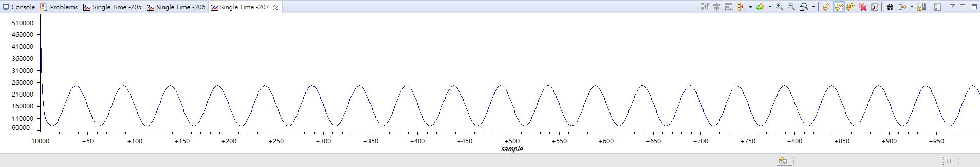
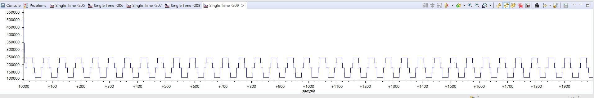
When I observed the datasheet, I found that DR[2:0] in the config1 register is the Output data rate. It means these bits determine the output data rate of the device. This represents the data transmission rate? If it is correct, ads1299 What is the sampling frequency of the channel? Can it be changed? How can it be changed?

Can you make a more complete description of DR[2:0] and channel sampling frequency?

  • Hello,

    The output data rate and channel sampling frequency are referring to the same thing. Data is available from all channels every 1 / fDATA seconds. 

    The DR[2:0] setting determines the oversampling (i.e. decimation) ratio of the digital filter. This is key to achieving low in-band noise in delta-sigma ADCs. For more information, please view our online training series on Designing with Delta-Sigma ADCs.

    Regards,

  • I have some questions.
    I used the signal generator to give a 10HZ sin wave, config1 was set to 0x96, and finally read out a perfect wave pattern.

     If I change to a sin wave of 10Hz, but the sampling rate is increased to 1K (config1 is set to 0x94), the result is as shown below.

    If I change to a sin wave of 10 Hz, but the sampling rate is increased to 4K (config1 is set to 0x92), the result is as shown below.

    But when I try to increase the sin wave to 50Hz,sampling rate is increased to 250 (config1 is set to 0x96), the data becomes as shown below.

    Theoretically, the higher the sampling frequency, the more complete the signal should be, but from the picture it seems that this is not the case. And I found that when DR[2:0] is set to 250SPS, there are 10 sin waves among 250 data points; but when DR[2:0] is set to 1k SPS, there are 20 sin waves, I think Should there be only 10 sin waves?

    I don't know what happened. I have tried to change the SPI rate, but it still has no effect.
    Why does the data cause problems when changing to 1k, 2k, 4k, 8k, 16k?

  • Hello,

    In the 4-kSPS example, it looks like there may be a problem with reading the SPI data. Check the SPI communication to make sure that you are reading the complete 24-bit channel data. It looks like the LSBs of the data are truncated.

    In the 250-SPS example, you will only see 5 samples per period of a 50-Hz sine wave. Although this satisfies the Nyquist criteria, this is not enough to see a smooth, clean sine wave.

    To confirm the data rate is configured correctly, check the period between /DRDY falling edges.

    Regards,